The HP Model 5326A/5327A is a series of electronic counters designed for precise measurement of frequency, period, time interval, average, and ratio. These instruments are versatile and can be used in various applications requiring accurate timing and frequency measurements.
Function Description
The HP 5326A/5327A counters are primarily used for pulse width, pulse repetition frequency, and phase measurements. They offer a comprehensive set of measurement capabilities, including:
- Frequency Measurement: Measures frequencies from 0 to 50 MHz (5326A) or 0 to 550 MHz (5327A). The 5326A uses a high-sensitivity 50-ohm input amplifier for precise measurements.
- Period Measurement: Measures the period of input signals.
- Time Interval Measurement: Measures the time between two events, such as the leading edge of one pulse and the leading edge of another.
- Average Measurement: Provides averaged measurements for improved accuracy.
- Ratio Measurement: Measures the ratio of two input frequencies.
- Totalize Measurement: Counts the number of events during a specified time interval.
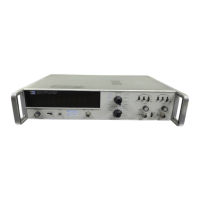
These instruments feature a 7-digit display (8-digit optional), which shows the measurement results. The display includes leading zero suppression, decimal point, and blanking for insignificant digits. Two independent input channels are provided for time interval measurements. Each input channel has an attenuator, trigger slope selector, level control, ac-dc coupling, and an oscilloscope marker output.
Important Technical Specifications
- Frequency Range:
- 5326A: 0 to 50 MHz
- 5327A: 0 to 550 MHz
- Sensitivity:
- 0.1 V rms sine wave (0.3 V p-p pulse)
- Minimum pulse width: 10 ns (can be decreased by 10 or 100 times using the attenuator switch).
- Input Impedance: 1 MΩ shunted by less than 25 pF.
- Dynamic Input Voltage Range: 0.1 V to 50 V rms (using attenuator setting) or ±5 Vdc (using time attenuator setting).
- Trigger Level: Adjustable from -3 V to +3 V (or -10 V to +10 V with attenuator setting). Trigger threshold can be set to input at maximum frequency.
- Overload Protection: 250 V rms on all attenuator settings, except 25 V rms on X1 above 50 kHz.
- Slope: Independent selection of positive or negative slope.
- Channel Inputs: Common or separate lines.
- Marker Outputs: Rear panel BNC's DTL pulse, low for approximately 2 µs after trigger point for A and B channels.
- Time Interval Average Self Check:
- Multiplier: 1 to 10^7
- Display: .1 µs to 100,000 ns
- Annunciator: µs, ms, ns, s
- Frequency A Self Check:
- Time Base: 1 µs to 10 s
- Display: 10.0 to 1,000,000.0 kHz
- Annunciator: MHz, kHz
- Period Average Self Check:
- Multiplier: 1 to 10^7
- Display: .1 µs to 100,000 ns
- Annunciator: µs, ms, ns, s
- Power Requirements: 115 or 230 volts ±10%, 50 to 60 Hz, 70 watts maximum.
- Weight: Net 16 lb (7.4 kg), Shipping 18 lb (8.2 kg).
- Dimensions: 16.51 cm (6-1/2 in.) high, 41.91 cm (16-1/2 in.) wide, 45.72 cm (18 in.) deep.
Usage Features
The HP 5326A/5327A counters are designed for ease of use with a logical front panel layout.
- Front Panel Controls: The front panel includes controls for:
- FUNCTION: Selects the desired measurement mode (e.g., frequency, period, time interval).
- TIME BASE/MULTIPLIER: Sets the measurement resolution and duration.
- CHECK FUNCTION: For self-test and calibration.
- SLOPE: Selects positive or negative trigger slope.
- SAMPLE RATE and HOLD: Controls the rate at which measurements are taken and allows holding a measurement on the display.
- LEVEL controls: Adjusts the trigger level for input channels.
- INPUT C switch (5327A only): For the higher frequency input channel.
- RESET: Resets the counter.
- Remote Programming: The instruments can be remotely programmed via DTL (Diode Transistor Logic) or TTL (Transistor-Transistor Logic) signals, allowing for automated testing and integration into larger systems. Option 004 provides remote programming capabilities.
- Display Features: The 7-digit display provides clear readouts with options for blanking insignificant digits and displaying units (µs, ms, seconds, or 10^n seconds).
- Input Channels: Two independent input channels (A and B) for time interval and ratio measurements, plus a third channel (C) for higher frequency measurements on the 5327A.
- Attenuator: Input attenuators provide flexibility in handling various signal levels.
- Trigger Level Adjustment: Precise control over trigger levels ensures accurate measurements even with noisy signals.
- Power Cord: A detachable power cord is supplied.
- Rack Mounting: The instruments can be mounted in a standard 19-inch equipment rack using an optional rack mount kit.
Maintenance Features
The manual provides detailed instructions for unpacking, inspection, repacking, storage, and installation, as well as information on basic maintenance and troubleshooting.
- Packaging and Shipping: Instructions are provided for proper packaging to prevent damage during shipment. This includes using protective wrapping paper, corrugated cartons, and foam inserts.
- Rack Installation: Steps are outlined for installing the instrument in a rack, including removing the tilt stand and attaching rack mount hardware.
- Line Voltage Conversion: Instructions are given for converting the instrument to operate on different line voltages (115 V or 230 V) by adjusting internal wiring and fuse.
- Power Cable: The counter is equipped with a detachable 3-wire power cable. Instructions are provided for connecting the cable to the instrument and to a grounded power outlet.
- Front Panel Controls Maintenance: The manual describes how to check and adjust front panel controls, including function selection, time base, sample rate, and input levels.
- Remote Programming Maintenance: Procedures for checking remote programming requirements and signals are detailed.
- Signal Conditioning Programming: Instructions for programming signal conditioning parameters like AC/DC coupling, slope, and attenuator settings.
- Blanking Defeat: The counter is designed to blank insignificant zeros. To defeat this feature for specific applications (e.g., using the instrument with an analog-to-digital converter), instructions are provided to reposition jumpers on the A9 Display board.
- Self-Check Procedures: The manual includes comprehensive self-check procedures for various functions, such as time interval average, frequency A, and period average. These checks help verify the instrument's accuracy and functionality.
- Troubleshooting: The manual would typically include a section on troubleshooting common issues, though specific details are not provided in the excerpt.
- Recycled Paper: The manual itself is printed on 100% recycled paper, indicating an environmental consciousness in the product's documentation.