13
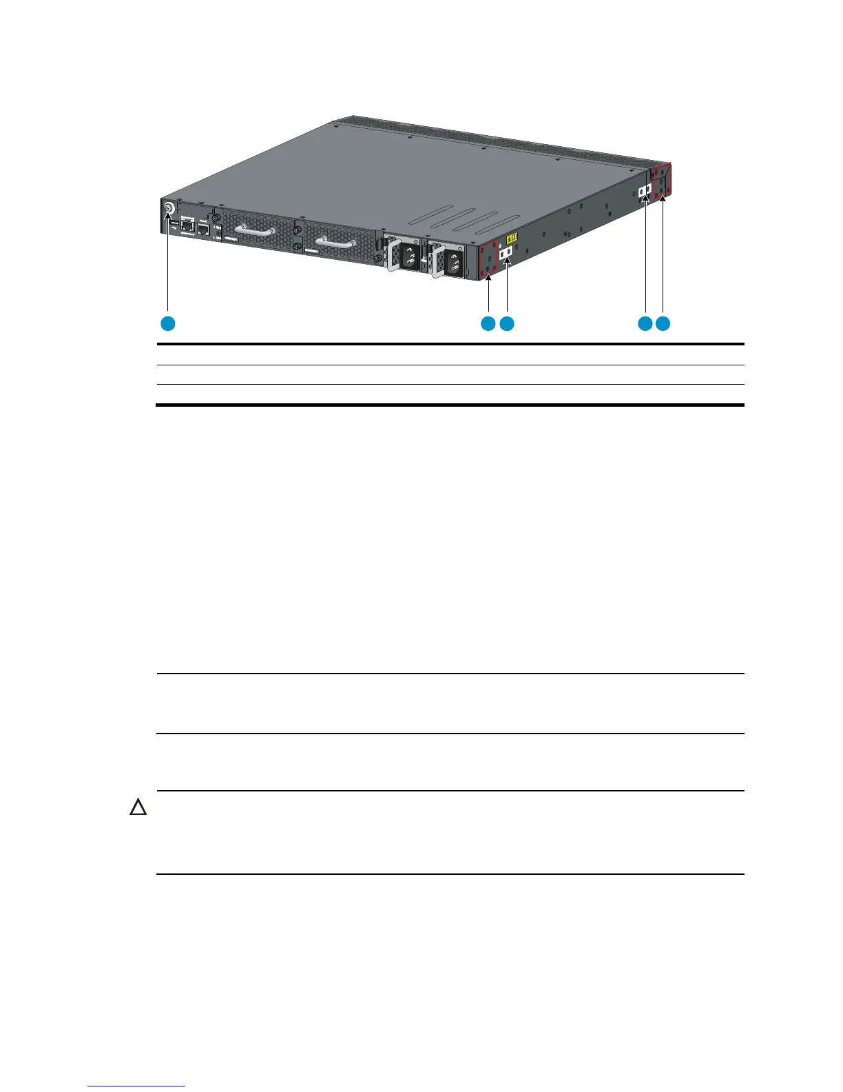
Figure 19 Identifying the mounting and grounding positions of the HP 5900AF-48G-4XG-2QSFP+
(1) Auxiliary grounding point 2 (2) Rear mounting position
(3) Primary
Attaching the mounting brackets and chassis rails to the chassis
To attach the mounting brackets and chassis rails to the switch chassis:
1. Align the mounting brackets with the screw holes in the rear mounting position or front mounting
position. See Figure 20 and Figure 21.
2. Use M4 screws (supplied with the switch) to attach the mounting brackets to the chassis.
3. Align the chassis rails with the rail mounting holes in the chassis:
{ If the mounting brackets are in the rear mounting position, align the chassis rails with the screw
holes at the front of the side panels. See Figure 20.
{ If the mounting brackets are in the front mounting position, align the chassis rails with the screw
holes at the rear of the side panels. See Figure 21.
4. Use M4 screws (supplied with the switch) to attach the chassis rails to the chassis.
NOTE:
Secure the mounting brackets and chassis rails to both sides of the chassis in the same way.
Connecting the grounding cable to the chassis
CAUTION:
The primary grounding point and auxiliary grounding point 1 are located on the left side panel. If you use
one of these grounding points, you must connect the grounding cable to the grounding point before you
mount the switch in the rack.
1
2
3
4 5
 Loading...