35
transceiver modules with optical fibers. If the IRF member switches are all in one equipment room, choose
twisted pair/SFP+/QSFP+ cables. For more information about available SFP+/QSFP+ cables and
transceiver modules, see "SFP+ port" and "QSFP+ port."
T
he following subsections describe several HP recommended IRF connection schemes, and all these
schemes use a ring topology.
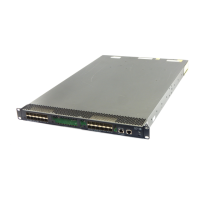
Connecting the IRF member switches in one rack
Use short-haul and long-haul SFP+ cables to connect the IRF member switches (four switches in this
example) in a rack as shown in Figure 47. T
he switches in the ring topology (as shown in Figure 48) are
in the same order as connected in the rack.
Figure 47 Connecting the switches in one rack
Figure 48 IRF fabric topology
Connecting the IRF member switches in a ToR solution
You can install IRF member switches in different racks side by side to deploy a top of rack (ToR) solution.
Figure 49 sho
ws an example for connecting four top of rack IRF member switches by using SFP+/QSFP+
cables, and SFP+/QSFP+ transceiver modules, and optical fibers. The topology is the same as Figure
48.
1
2
3
4
 Loading...