5-24 Figure 5-4B shows a correct method of measuring
the output ripple of a constant voltage power supply
using a single-ended scope. The ground loop path is
broken by floating the power supply output. To ensure
that no potential difference exists between the supply
and the oscilloscope, it is recommended that they both
be plugged into the same ac power bus. If the same bus
cannot be used, both ac grounds must be at earth
ground potential.
5-25 Either a twisted pair or, preferably, a shielded two-
wire cable should be used to connect the output terminals
of the power supply to the vertical input terminals of the
scope. When using a twisted pair, care must be taken that
one of the two wires is connected to the grounded input
terminal of the oscilloscope to ensure that the supply
output is safely grounded. When using shielded two-wire, it
is essential for the shield to be connected to ground at one
end only to prevent ground current flowing through this
shield from inducing a signal in the shielded leads.
5-26 To verify that the oscilloscope is not displaying
ripple that is induced in the leads or picked up from the
grounds, the (+) scope lead should be shorted to the (-)
scope lead at the power supply terminals. The ripple value
obtained when the leads are shorted should be subtracted
from the actual ripple measurement.
5-27 In most cases, the single-ended scope method of
Figure 5-4B will be adequate to eliminate extraneous ripple
so that a satisfactory measurement may be obtained.
However, in more stubborn cases (or if high frequency
noise up to 20 MHz must be measured). it may be
necessary to use a differential scope with floating input as
shown in Figure 5-4C. If desired, two single-conductor
shielded cables may be substituted in place of the shielded
two-wire cable with equal success. Because of its common
mode rejection. a differential oscilloscope displays only the
difference in signal between its two vertical input terminals,
thus ignoring the effects of any common mode signal pro-
duced by the difference in the ac potential between the
power supply case and scope case. Before using a differen-
tial input scope in this manner, however, it is imperative
that the common mode rejection capability of the scope be
verified by shorting together its two input leads at the
power supply and observing the trace on the CRT. If this
trace is a straight line, then the scope is properly ignoring
any common mode signal present. If this trace is not a
straight line, then the scope is not rejecting the ground
signal and must be realigned in accordance with the manu-
facturer's instructions until proper common mode rejection
is attained
5-28 Measurement Procedure. To measure the ripple
and noise on each supply output, follow the steps
below, If a high frequency noise measurement is desired,
an oscilloscope with sufficient bandwidth (20 MHz) must
be used. Ripple and noise measurements can be made at
any input ac line voltage combined with any dc output
voltage and load current within rating.
a. Connect an oscilloscope or rms voltmeter across an
output of the supply as shown in Figures 5-4B or 5-4C.
b. Energize the supply and observe the oscilloscope or
meter indication. The ripple and noise should not be
greater than 0.35mV rms or 1.5mV peak-to-peak.
c. Repeat for the remaining supply outputs.
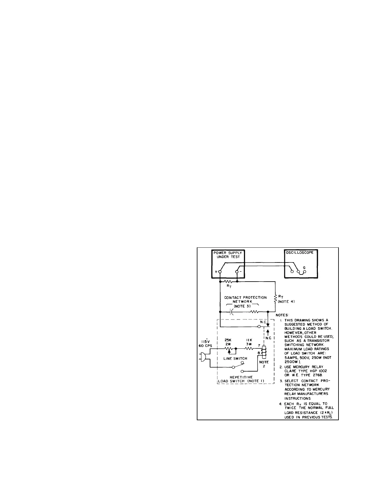
5-30 Measurement Techniques. Care must be taken in
switching the load resistance on and off. A hand-operated
switch in series with the load is not adequate since the re-
sulting one-shot displays are difficult to observe on most
oscilloscopes and the arc energy occurring during switching
completely masks the display with a noise burst.
Transistor
load switching devices are expensive if reasonably rapid load
Fi
ure 5-5. Load Transient Recover
Time, Test Setu
5-5
5-29 Load Transient Recovery Time
Definition: The time "X" for output voltage
recovery to within "Y" millivolts of the nominal output
voltage following a "Z" amp step change in load current,
where: "Y" equals 15mV, and "Z" is the specified load
current change, equal to half of the current rating of the
supply. The nominal output voltage is defined as the dc
level halfway between the static output voltage before
and after the imposed load change.