SECTION VII
CIRCUIT DIAGRAMS
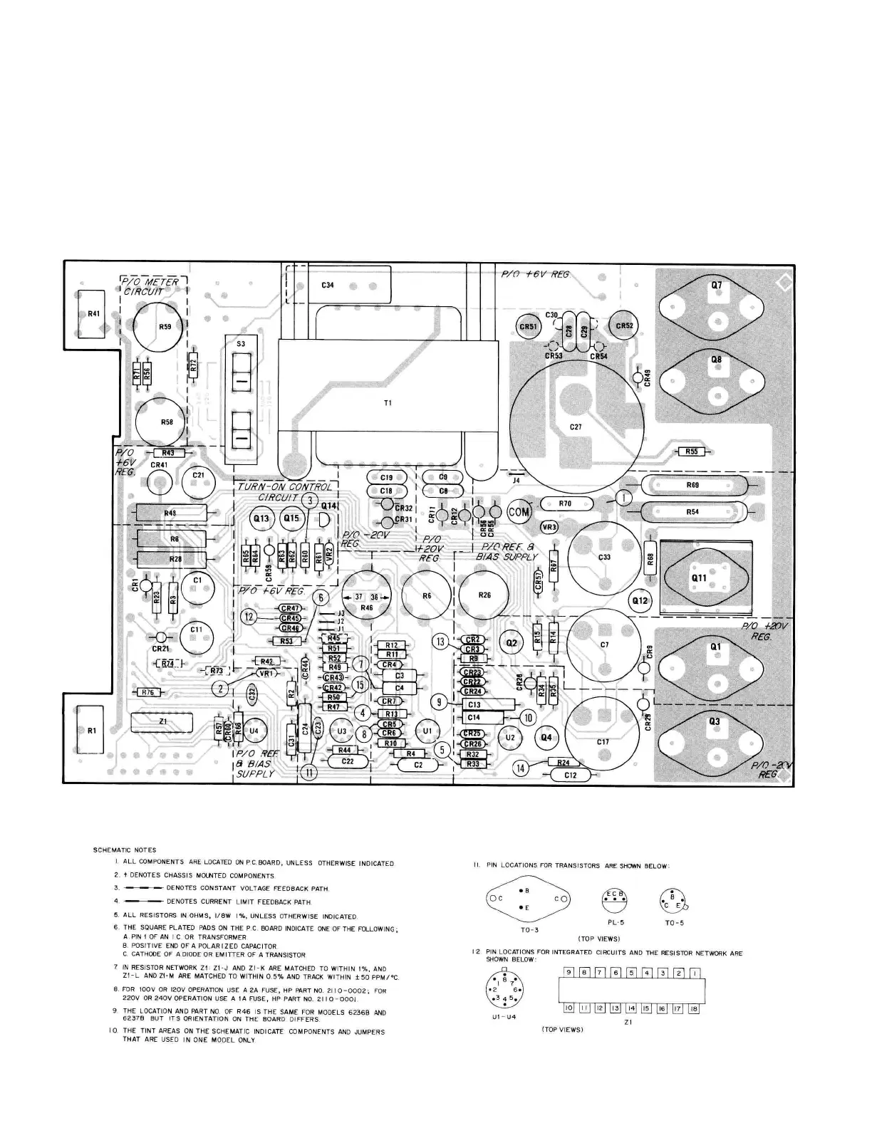
7-2 The component location diagram for power supply
Models 6236B and 6237B is given below. The illustration
shows the physical locations and reference designations
of parts mounted on the printed circuit card. (Not. all parts
are used in both models.)
7.4 Figure 7.1 is a combined schematic diagram of the
6236B and 6237B. The test points (circled numbers)
shown on the schematic correspond to those on the
component location diagram and in the troubleshooting
procedure in Section V. The tinted areas on the schematic
indicate components and jumpers used in one model only.
Models 6236B and 6237B, Component locations
7-1
7.3 SCHEMATIC DIAGRAM
7-1 COMPONENT LOCATION DIAGRAM