Operation
0
•
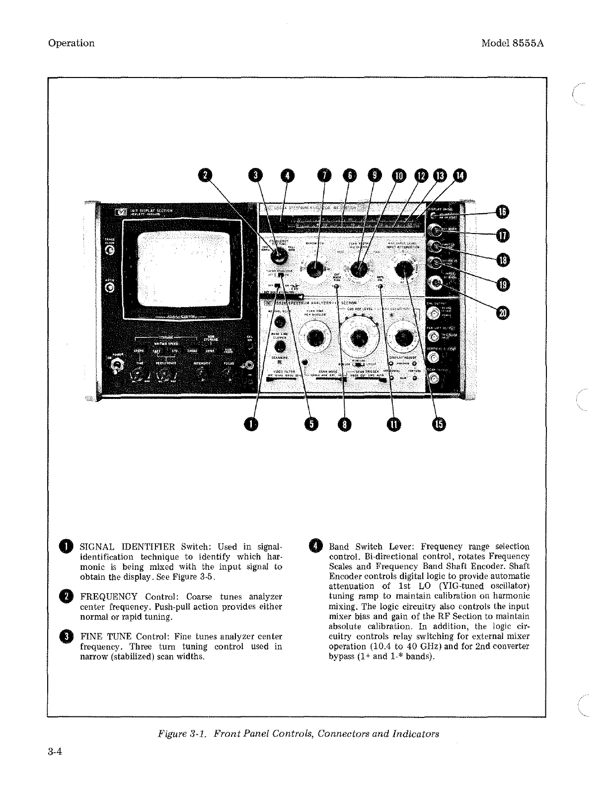
SIGNAL IDENTIFIER Switch: Used in signal-
identification technique to identify which
har-
monic
is
being mixed with the
input
signal to
obtain the display.
See Figure 3-5.
FREQUENCY Control: Coarse tunes analyzer
center frequency.
Push-pull action provides either
normal or rapid tuning.
FINE TUNE Control: Fine tunes analyzer center
frequency. Three
tum
tuning control used in
narrow (stabilized) scan widths.
0
Model8555A
Band Switch Lever: Frequency range selection
control. Bi-directional control, rotates Frequency
Scales and Frequency Band Shaft Encoder. Shaft
Encoder controls digital logic to provide automatic
attenuation of 1st
LO
(YIG-tuned oscillator)
tuning ramp to maintain calibration on harmonic
mixing. The logic circuitry also controls the input
mixer bias and gain
of
the RF Section to maintain
absolute calibration. In addition, the logic
cir-
cuitry controls relay switching for external mixer
operation (10.4
to
40 GHz) and for 2nd converter
bypass
(1
+and
1-* bands).
Figure 3-1.
Front
Panel Controls, Connectors and Indicators
3-4