Model8555A
0
0
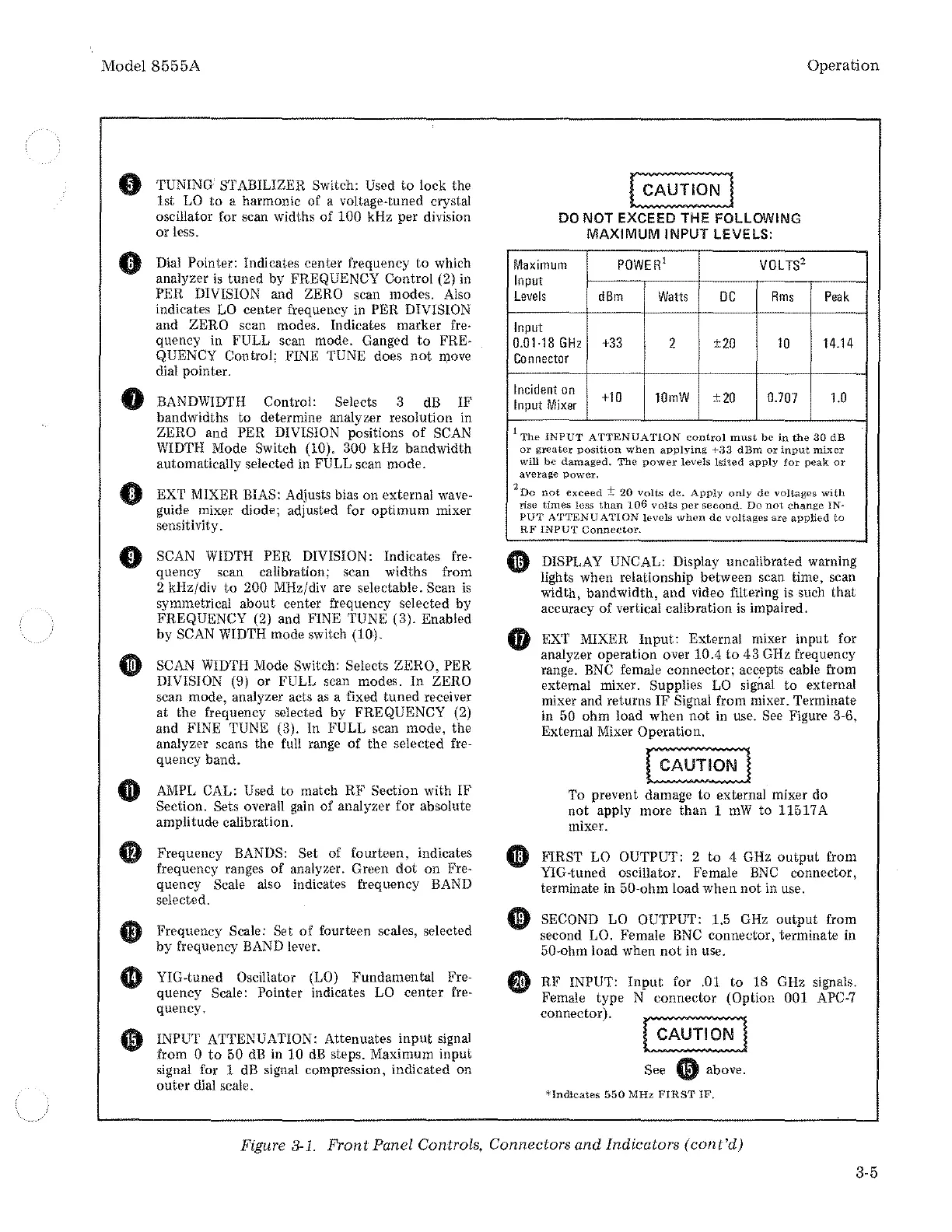
TUNING STABILIZER Switch: Used
to
lock the
lst
LO
to
a harmonic of a
voltage~tuned
crystal
oscillator for scan widths
of
100
kHz per division
or
less.
Dial Pointer: Indicates center frequency
to
which
analyzer
is
tuned by FREQUENCY Control (2) in
PER DIVISION and ZERO scan modes.
Also
indicates
LO
center frequency in PER DIVISION
and ZERO scan modes. Indicates marker fre·
quency in FULL scan mode. Ganged
to
FRE-
QUENCY Control;
Fll'\IE
TUNE does
not
move
dial pointer.
BANDWIDTH Control: Selects 3
dB
IF
bandwidths to determine analyzer resolution in
ZERO and PER DIVISION positions
of
SCAN
WIDTH
Mode Switch (10). 300 kHz bandwidth
automatically selected in FULL scan mode.
EXT MIXER
BIAS: Adjusts bias on external wave-
guide mixer diode; adjusted for optimum mixer
sensitivity.
SCAN
WIDTH
PER DIVISION: Indicates
fre-
quency scan calibration; scan widths from
2 kHz/div
to
200 MHz/div are selectable. Scan
is
svmmetrical about center frequency selected by
FREQUENCY (2) and FINE TUNE (3). Enabled
by
SCAN
WIDTH
mode switch (10).
SCAN
WIDTH
Mode Switch: Selects ZERO, PER
DIVISION (9)
or
FULL scan modes.
In
ZERO
scan mode, analyzer acts
as
a fixed tuned receiver
at
the frequency selected by FREQUENCY (2)
and FINE
TUNE (3). In FULL scan mode, the
analyzer scans the full range of the selected
fre-
quency band.
AMPL
CAL: Used to match
RF
Section with IF
Section. Sets overall
gain
of analyzer for absolute
amplitude calibration.
Frequency
BANDS: Set of fourteen, indicates
frequency ranges
of
analyzer. Green
dot
on Fre-
quency Scale also indicates frequency BAND
selected.
Frequency
Scale: Set
of
fourteen scales, selected
by frequency BAND lever.
YIG-tuned
Oscillator (LO) Fundamental Fre-
quency Scale: Pointer indicates LO center fre-
quency.
INPUT ATTENUATION: Attenuates
input
signal
from
0
to
50
dB
in 10
dB
steps. Maximum input
signal for 1
dB
signal compression, indicated on
outer
dial scale.
~~:~~~~]
DO
NOT
EXCEED THE FOLLOWING
MAXIMUM
INPUT
LEVELS:
Maximum
POWER
1
VOL
TS
2
Input
Levels
dBm
Watts
DC
Rms
Input
0.01-18
GHz
+33
2
±20
10
Connector
Incident
on
+10
10mW
±20
0.707
Input
Mixer
Operation
Peak
14.14
1.0
1
The
INPUT
ATTENUATION
control
must
be
in
the
30
dB
or
greater
position
when
applying
+33
dBm
or
input
mixer
will
be
damaged.
The
power
levels
!sited
apply
for
peak
or
average
power.
2
Do
not
exceed±
20
volts
de.
Apply
only
de
voltages
with
rise
times
less
than
106
volts
per
second.
Do
not
change
IN-
PUT
ATTENUATION
levels
when
de
voltages
are
applied
to
RF
INPUT
Connector.
DISPLAY UNCAL: Display uncalibrated warning
lights when relationship between scan time, scan
width, bandwidth, and video filtering
is
such
that
accuracy of vertical calibration
is
impaired.
EXT MIXER
Input:
External mixer input for
analyzer operation over
10.4
to
43 GHz frequency
range.
BNC
female connector; acc.epts cable from
external mixer.
Supplies
LO
signal to external
mixer and returns
IF
Signal from mixer. Terminate
in
50 ohm load when
not
in use. See Figure 3-6,
External Mixer
Operation.
'I'o
prevent damage to external mixer do
not
apply more than 1
mW
to 11517A
mixer.
F1RST LO OUTPUT: 2
to
4 GHz
output
from
YIG-tuned oscillator. Female
BNC
connector,
terminate in 50-ohm load when
not
in use.
SECOND
LO
OUTPUT: 1.5
GHz
output
from
second
LO. Female
BNC
connector, terminate in
50*ohm load when
not
in use.
RF
INPUT:
Input
for .01 to 18 GHz signals.
Female
type
N connector (Option 001
APC-7
connector).
See 0 above.
*Indicates
550
MHz
FIRST
IF,
Figure
3-1.
Front Panel Controls, Connectors and Indicators
(cont'd)
3-5