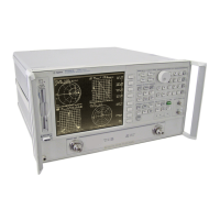
HP 8753D
System Operation
Network
analyzers
measure
the
reection and
transmission characteristics
of devices
and
networks
.
A
network
analyzer
test
system consists
of the
following:
source
signal-separation
devices
receiver
display
The
analyzer
applies
a
signal
that
is transmitted
through the
test device
,
or
reected
from
its
input,
and
then compares
it with
the incident
signal generated
by
the
swept
RF
source
.
The
signals
are
then applied
to a
receiver for
measurement, signal
processing,
and
display
.
The
HP
8753D vector
network analyzer
integrates a
high resolution
synthesized
RF
source
,
test
set,
and a
dual channel
three-input receiver
to measure
and
display
magnitude
,
phase
,
and
group
delay of
transmitted and
reected power
.With
Option
010,
the
analyzer
has
the
additional capability
of transforming
measured
data
from
the
frequency
domain
to
the
time
domain.
Other
options
are
explained
in
Chapter 1,
\HP
8753D
Description
and
Options
."
Figure
6-1
is
a
simplied
block
diagram
of
the
network
analyzer
system.
A
detailed
block
diagram
of
the
analyzer
is
provided
in
the
HP
8753D
Network
Analyzer
Service
Guide
together
with
a
theory
of
system
operation.
Figure
6-1.
Simplied
Block
Diagram
of
the
Network
Analyzer
System
The Built-In
Synthesized Source
The analyzer's built-in synthesized source produces a swept RF signal or CW (continuous wave)
signal in the range of 30 kHz to 3.0 GHz. The HP 8753D Option 006 is able to generate signals
up
to 6 GHz. The RF output power is leveled by an internal ALC (automatic leveling control)
circuit. T
o achieve frequency accuracy and phase measuring capability
,
the analyzer is phase
locked to a highly stable crystal oscillator
.F
or this
purpose, a portion of the transmitted signal
is routed to the R channel input of the receiver
, where
it is sampled by the phase detection
loop and fed back to the source
. Some portion of the RF
source signal must always be sent to
the R channel input. The level must be between 0 dB and -35 dBm.
The Source Step Attenuator
The step attenuator contained in the source is used to adjust the power level to the test device
without changing the level of the incident power in the reference path.
6-2 Application and Operation Concepts



 To Next Page