EasyManua.ls Logo

HP 8753D - Page 295

HP 8753D
678 pages
Print Icon
To Next Page IconTo Next Page
To Previous Page IconTo Previous Page
Loading...
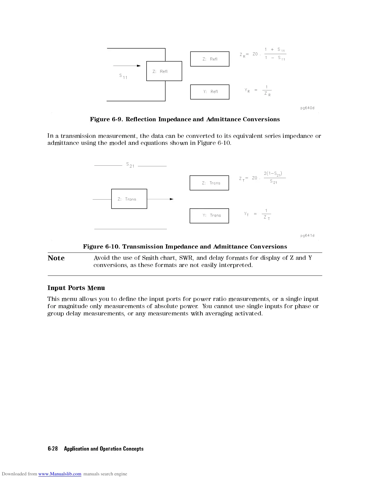
Figure
6-9.
Reection
Impedance
and
A
dmittance
Conversions
In
a transmission
measurement,
the
data
can
be
converted
to
its
equivalent
series
impedance
or
admittance
using
the
model
and
equations
shown
in
Figure
6-10
.
Figure
6-10.
Transmission
Impedance and
A
dmittance
Conversions
Note
A
void
the
use
of
Smith
chart,
SWR,
and
delay
formats
for
display
of
Z
and
Y
conversions
,
as
these
formats
are
not
easily
interpreted.
Input
P
orts
Menu
This
menu
allows
you
to
dene
the
input
ports for
power ratio
measurements,
or
a
single
input
for magnitude
only measurements
of absolute
power.
Y
ou
cannot
use
single
inputs
for
phase
or
group delay
measurements,
or any
measurements with
averaging
activated.
6-28 Application and Operation Concepts