Scale Reference
Menu
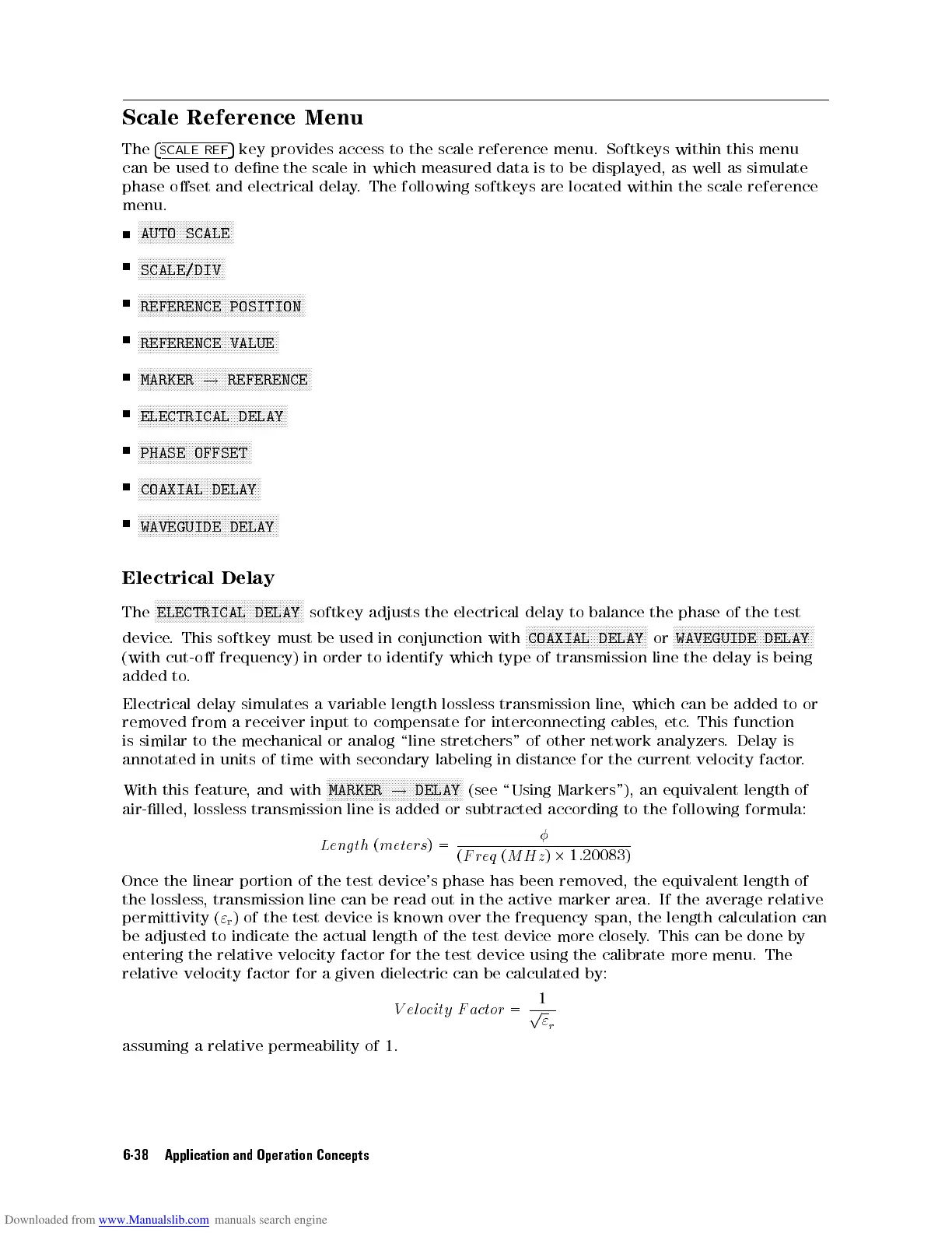
The
4
SCALE
REF
5
key provides
access to
the
scale
reference
menu.
Softkeys
within
this
menu
can
be used
to dene
the
scale
in
which
measured
data
is
to
be
displayed,
as
well
as
simulate
phase
oset and
electrical delay
.
The
following
softkeys
are
located
within
the
scale
reference
menu.
N
NN
NN
N
N
N
N
N
N
N
N
N
N
N
N
N
N
N
N
N
NN
NN
NN
NN
N
N
AUTO
SCALE
N
N
N
N
N
N
N
N
N
N
N
N
N
N
N
N
NN
NN
NN
N
N
N
N
N
N
N
SCALE/DIV
N
N
N
N
N
N
N
N
NN
NN
NN
N
N
N
N
N
N
N
N
N
N
N
N
N
N
N
N
N
N
N
NN
NN
NN
N
N
N
N
N
N
N
N
N
N
N
N
N
N
N
N
N
REFERENCE
POSITION
NN
NN
NN
NN
N
N
N
N
N
N
N
N
N
N
N
N
N
N
N
N
N
NN
NN
NN
NN
N
N
N
N
N
N
N
N
N
N
N
N
N
N
REFERENCE VALUE
NN
NN
N
N
N
N
N
N
N
N
N
N
N
N
N
N
N
N
N
NN
NN
NN
NN
N
N
N
N
N
N
N
N
N
N
N
N
N
N
N
N
N
NN
NN
NN
NN
N
N
N
N
MARKER
!
REFERENCE
N
N
N
N
N
N
N
N
N
N
N
N
N
NN
NN
NN
NN
N
N
N
N
N
N
N
N
N
N
N
N
N
N
N
N
N
NN
NN
NN
NN
N
N
N
N
ELECTRICAL
DELAY
N
N
N
N
N
N
N
N
N
N
N
N
N
NN
N
N
N
N
N
N
N
N
N
N
N
N
N
N
N
N
N
N
N
N
N
N
N
PHASE
OFFSET
N
N
N
N
N
N
N
N
N
N
N
N
N
N
NN
NN
NN
N
N
N
N
N
N
N
N
N
N
N
N
N
N
N
N
N
N
N
NN
COAXIAL
DELAY
N
N
N
N
N
N
N
N
NN
NN
N
N
N
N
N
N
N
N
N
N
N
N
N
N
N
N
N
N
N
N
N
NN
NN
N
N
N
N
N
N
N
N
N
N
WAVEGUIDE
DELAY
Electrical
Delay
The
N
N
N
N
N
N
N
N
N
N
N
N
N
N
N
N
N
NN
N
N
N
N
N
N
N
N
N
N
N
N
N
N
N
N
N
N
N
N
N
N
N
NN
N
N
N
N
N
N
ELECTRICAL
DELAY
softkey
adjusts
the
electrical
delay
to
balance
the
phase
of
the
test
device
.
This
softkey
must
be
used
in
conjunction
with
N
N
N
N
N
N
N
N
N
N
N
N
N
NN
N
N
N
N
N
N
N
N
N
N
N
N
N
N
N
N
N
N
N
N
N
N
N
NN
N
COAXIAL
DELAY
or
N
N
N
N
N
N
N
N
N
N
N
N
N
NN
N
N
N
N
N
N
N
N
N
N
N
N
N
N
N
N
N
N
N
N
N
N
N
NN
N
N
N
N
N
N
N
WAVEGUIDE
DELAY
(with cut-o
frequency)
in
order
to
identify
which
type
of
transmission
line
the
delay
is
being
added to
.
Electrical delay
simulates a
variable
length
lossless
transmission
line
,
which
can
be
added
to
or
removed
from
a
receiver
input
to
compensate
for
interconnecting
cables
,
etc
.
This
function
is
similar
to
the
mechanical
or
analog
\line
stretchers"
of
other
network
analyzers
.
Delay
is
annotated
in
units
of
time
with
secondary
labeling
in
distance
for
the
current
velocity
factor
.
With this
feature,
and with
N
N
NN
NN
NN
NN
N
N
N
N
N
N
N
N
N
N
N
N
N
N
N
N
N
NN
NN
NN
NN
N
N
N
N
N
N
N
N
N
N
N
MARKER
!
DELAY
(see
\Using Markers"),
an
equivalent
length
of
air-lled,
lossless
transmission
line
is
added
or
subtracted
according
to
the
following
formula:
Leng
th
(
meter
s
)
=
(
Freq
(
MHz
)
2
1
:
20083)
Once the linear portion of the test device's phase has
been removed, the equivalent length of
the lossless
, transmission line can be read out in
the active marker area. If the average relative
permittivity (
"
r
) of the test device is known over the frequency span, the length calculation can
be adjusted to indicate the actual length of the test device more closely
. This can be done by
entering the relative velocity factor for the test device using the calibrate more menu. The
relative velocity factor for a given dielectric can be calculated by:
V elocity F actor
=
1
p
"
r
assuming a relative permeability of 1.
6-38 Application and Operation Concepts


 To Next Page
 Loading...