EasyManua.ls Logo

HP 8753D - Page 307

HP 8753D
678 pages
Print Icon
To Next Page IconTo Next Page
To Previous Page IconTo Previous Page
Loading...
Dual
Channel
Mode
The
N
NN
NN
NN
NN
NN
N
N
N
N
N
N
N
N
N
N
N
NN
NN
NN
NN
NN
NN
NN
N
N
N
N
N
N
N
N
N
N
N
NN
N
DUAL
CHAN on
OFF
softkey
toggles between
display of
both
measurement
channels
or
the active
channel only
. This
is
used
in
conjunction
with
NN
NN
NN
NN
N
N
N
N
N
N
N
N
N
N
N
N
N
NN
NN
NN
NN
NN
NN
N
N
N
N
N
N
N
N
N
N
N
N
N
NN
NN
NN
N
SPLIT DISP
ON off
in the
display
more
menu to
display
both
channels
.
With
N
NN
NN
N
N
N
N
N
N
N
N
N
N
N
N
N
NN
NN
NN
NN
NN
NN
N
N
N
N
N
N
N
N
N
N
N
N
N
NN
NN
NN
NN
NN
SPLIT
DISP on
OFF
the
two
traces
are
overlaid
on
a
single
graticule
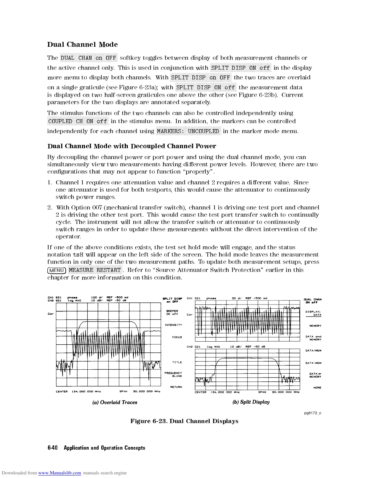
(see
Figure
6-23
a);
with
NN
NN
N
N
N
N
N
N
N
N
N
N
N
NN
NN
NN
NN
NN
NN
NN
N
N
N
N
N
N
N
N
N
N
N
NN
NN
NN
NN
NN
NN
N
SPLIT
DISP
ON
off
the
measurement
data
is displayed
on two
half-screen graticules
one
above
the
other
(see
Figure
6-23
b).
Current
parameters for
the two
displays are
annotated
separately
.
The stimulus
functions
of
the
two
channels
can
also
be
controlled
independently
using
N
NN
NN
NN
N
N
N
N
N
N
N
N
N
N
N
N
N
N
N
N
N
N
N
NN
NN
NN
N
N
N
N
N
N
N
N
N
N
N
N
N
N
N
N
N
N
N
NN
COUPLED
CH ON
off
in
the stimulus
menu.
In
addition,
the
markers
can
be
controlled
independently for
each channel
using
NN
NN
NN
N
N
N
N
N
N
N
N
N
N
N
N
N
N
N
N
N
NN
NN
NN
NN
N
N
N
N
N
N
N
N
N
N
N
N
N
N
N
N
N
NN
NN
NN
NN
MARKERS: UNCOUPLED
in the
marker
mode
menu.
Dual
Channel
Mode
with
Decoupled
Channel
P
ower
By
decoupling
the
channel
power
or
port
power
and
using
the
dual
channel
mode
,
you
can
simultaneously
view
two
measurements
having
dierent
power
levels
.
However
,
there
are
two
congurations
that
may
not
appear
to
function
\properly".
1.
Channel
1
requires
one
attenuation
value
and
channel
2
requires
a
dierent
value
.
Since
one attenuator
is
used
for
both
testports
,
this
would
cause
the
attenuator
to
continuously
switch power
ranges
.
2.
With
Option
007
(mechanical
transfer
switch),
channel
1
is
driving
one
test
port and
channel
2
is
driving
the
other
test
port.
This
would
cause
the
test
port
transfer switch
to continually
cycle
.
The
instrument
will
not
allow
the
transfer
switch
or
attenuator
to
continuously
switch
ranges
in
order
to
update
these
measurements
without
the
direct
intervention
of
the
operator
.
If
one
of
the
above
conditions
exists
,
the
test set
hold
mode
will
engage
,
and
the
status
notation
tsH
will
appear
on
the
left
side
of
the screen.
The
hold
mode
leaves
the
measurement
function
in
only
one
of
the
two
measurement
paths
.T
o update
both
measurement
setups
,
press
4
MENU
5
N
N
N
N
N
N
N
N
N
N
N
N
N
N
N
N
N
N
N
NN
NN
N
N
N
N
N
N
N
N
N
N
N
N
N
N
N
N
N
N
N
N
N
NN
N
MEASURE
RESTART
.
Refer
to
\Source
Attenuator
Switch
Protection"
earlier
in
this
chapter
for
more
information
on
this
condition.
Figure 6-23. Dual Channel Displays
6-40 Application and Operation Concepts