Service
Model
89038
SCHEMATIC SYMBOLOGY
AND
SCHEMATIC DIAGRAM
NOTES
Tahk
8-6.
Schcntatic Diagram
Noicy
(I
0
o/'
I I)
a
Active High Input
Active
I
High Output
-c7
Active
Low input
Active
El-
Low Output
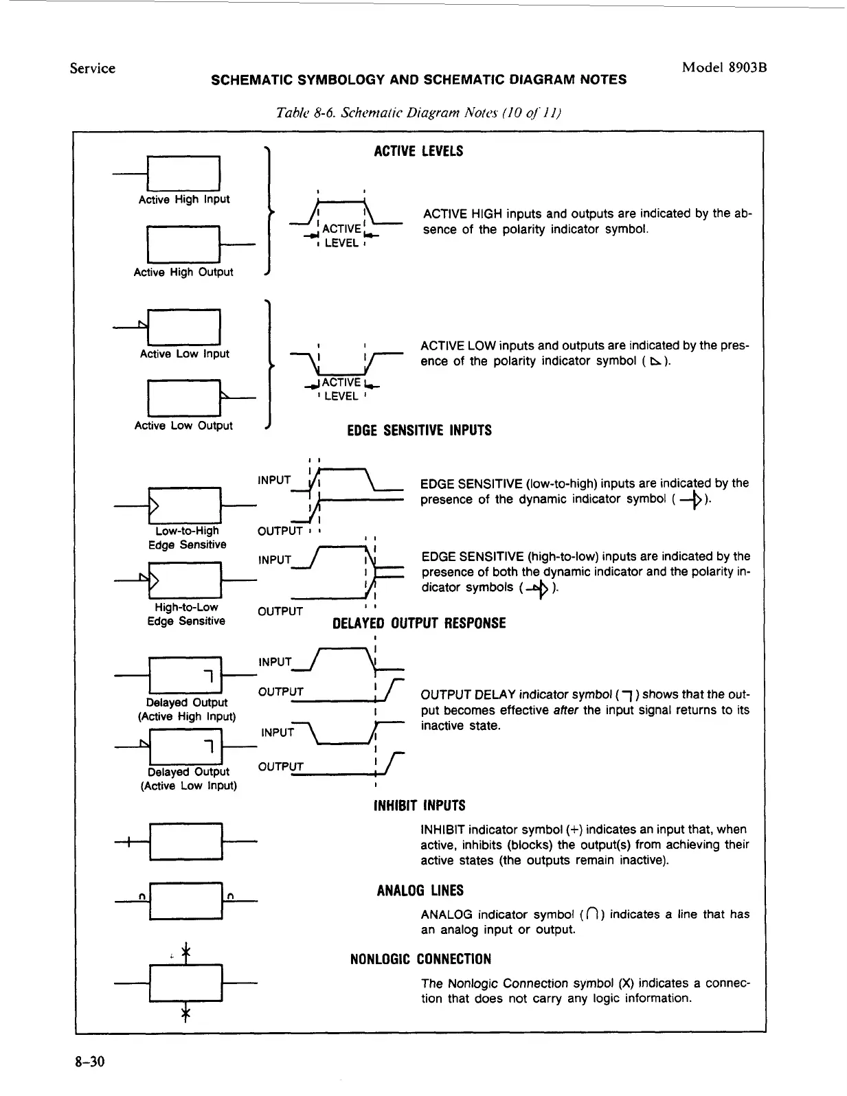
ACTIVE LEVELS
'
J-L
ACTIVE HIGH inputs and outputs are indicated by the ab-
ACTIVE
Lc
sence of the polarity indicator symbol.
I
LEVEL
I
ACTIVE LOW inputs and outputs are indicated by the pres-
ence of the polarity indicator symbol
(
h).
7\1
4
ACTIVE
4
I
LEVEL
I
EDGE SENSITIVE INPUTS
II
lNpUTq-L
EDGE SENSITIVE (low-to-high) inputs are indicated by the
presence of the dynamic indicator symbol
(-0).
Low-to-High OUTPUT
I
I
Edge Sensitive
+-,
iNPUTJ-k EDGE SENSITIVE (high-to-low) inputs are indicated by the
presence of both the dynamic indicator and the polarity in-
dicator symbols
(
+
).
11
Hig h-to-Low OUTPUT
Edge Sensitive
DELAYED OUTPUT RESPONSE
i
NPuTJ-L
I
*OUTPUT Delayed Output
I
f
OUTPUT
DELAY
indicator symbol
(1)
shows that the
out-
put becomes effective after the input signal returns to its
inactive state.
I
(Active High input)
-OUTPUT Delayed Output
f
(Active
Low Input)
I
INHIBIT INPUTS
INHIBIT indicator symbol
(+)
indicates an input that, when
active, inhibits (blocks) the output(s) from achieving their
active states (the outputs remain inactive).
ANALOG LINES
ANALOG indicator symbol
(n)
indicates a line that has
an analog input or output.
NONLOGIC CONNECTION
The Nonlogic Connection symbol
(X)
indicates a connec-
tion that does not carry any logic information.
8-30