Service Model
8903B
The Floating Output Amplifier generates a differential output signal, that is, a signal not referenced
to
ground.
Either OUTPUT terminal
[HIGH
or
LOW)
may be grounded or floated up
to
10
Vpk. This feature is useful for
breaking up ground loops, summing signals, and adding dc offsets to the output. Attenuator
B
is also floating.
For
instruments with serial prefix 2730A and below, the output impedence is selected
by
a non-programmable,
front panel IMPEDENCE switch for either
500
or
600R.
For instruments with serial prefix 2742A and above,
the output impedance can be selected from the front panel
or
via
HP-IB
by
using Special Functions
(47.X).
The Over-Voltage Protect circuit protects the output circuits from the inadvertent application
of
a reverse
voltage to either the
HIGH
or
LOW
OUTPUT
connector. The reverse voltage
is
sensed
by
an over-voltage
detector, which opens
two
output relays. The relays automatically reset about
1s
after the overvoltage is
removed. The Voltage Clamp protects the output circuits during the time between the application
of
the
reverse
voltage and the opening
of
the relay contacts.
Counter
When the frequency
of
the input signal
or
Oscillator is to be counted, two sub-counters
(the
Cycle and Clock
Counters) operate simultaneously. The signal itself
is
directed into
the
Cycle Counter.
In
the case
of
counting
the input signal, the signal
is
first routed through the Counter Input Schmitt Trigger which converts
the
analog
signal into square wave pulses which are compatible with the Cycle Counter. The
2
MHz
Clock signal is
directed into the Clock Counter.
To
count frequency, the Controller first sets the Clock Counter Gate switch
to
route the path from the
Frequency Gate switch into the Clock Counter. Then, the Controller arms the Cycle Counter Gate and
Frequency Gate switches, and the first signal pulse closes the switches. Both counters (which were previously
cleared) then begin to accumulate counts. The Cycle Counter is
a
divide by
32,
the Clock Counter is a divide
by
2048.
The overflow or carry pulses of each counter are counted by the Controller.
After
a pre-determined
minimum number of carries from the Clock Counter and at least one carry from the Cycle Counter, the
Frequency Gate and Cycle Counter Gate switches are disabled by the Controller. The first signal piilse opens
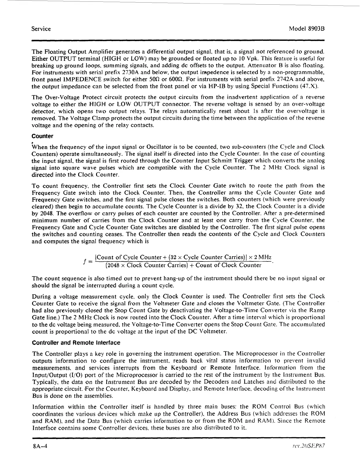
the switches and counting ceases. The Controller then reads the contents of the Cycle and Clock Counters
and computes the signal frequency which is
t
(Count of Cycle Counter
+
(32
x
Cycle Counter Carries)/
x
2
MHz
(2048
x
Clock Counter Carries)
+
Count
of
Clock Counter
=
The count sequence is also timed
out
to
prevent hang-up of the instrument should there be
no
input
signal
or
should the signal be interrupted during a count cycle.
During
a
voltage measurement cycle.
only
the Clock Counter is used.
The
Controller first sets the Clock
Counter Gate to receive the signal from the Voltmeter Gate and closes the Voltmeter Gate. (The Controller
had also previoiisly closed the Stop Count Gate by deactivating the Voltage-to-Time Converter
via
the Ramp
Gate line.) The 2
MHz
Clock is now routed into the Clock Counter, After a time interval which is proportional
to the dc voltage being measured. the Voltage-to-Time Converter opens the Stop Count Gate. The accirmLilated
count is proportional to the dc voltage at the input of the DC Voltmeter.
Controller
and
Remote Interface
The Controller plays
a
key role
in
governing the instrument operation. The Microprocessor
in
the Controller
outputs information to configure the instrument, reads back vital status
in
formation
to
prevent invalid
measurements, and services interrupts from the Keyboard
or
Remote Interface.
I
nfornintion from the
Input/Output
(I/O)
port of the Microprocessor is carried
to
the rest
of
the instrument
by
the Instrument
BLIS.
Typically, the data
on
the
Instrument
BLIS
are decoded by the Decoders and Latches
and
distributed
to
the
appropriate circuit. -For the Counter, Keyboard and Display, and Remote Interface. decoding
of
the Instrument
BUS
is
done
on
the assemblies.
Information
within the Controller itself
is
handled by three main buses: the ROM Control
Bus
(which
coordinates the various devices which make
LIP
the
Controller), the Address
Bus
(which addresses the
ROM
and RAM), and the Data
BLIS
(which carries information
to
or
from
the ROM and
RAM).
Since
the
Remote
Interface contains some Controller devices, these buses are also distributed to it.
8A-4
r.c'~'.2oSl:PH7
 Loading...


