Model 89038
PRINCIPLES
OF
OPERATION---SERVICE SHEET
1
Service
SERVICE
SHEET
1
---A2
Input Amplifier
Assembly
(Input Circuits)
PRINCIPLES
OF
OPERATION
General
This portion
of
the Input Amplifier Assembly (A2) contains the AC/DC Switch, Input Attenuator, Over-Voltage
Protection, and Differential-to-Single-Ended Amplifier. These and the other circuits on the Input Amplifier
Assembly condition the signal to be suitable to drive the
Notch
Filter and Output Amplifier.
Input Circuits and Input Attenuator
The
signals at the
HIGH
and
LOW
INPUT connectors are filtered by
RFI
filters
A13L2
and
A13C16
and
A13L3 and A13C15. The INPUT connectors are both floating. The
LOW
INPUT can be shorted
to
ground by
chassis part S3. The inputs are ac coupled by C2 and C88 except in the dc
level
measurement mode where the
capacitors are effectively shorted
by
R2 and R104 which are switched in by K7.
The High and
Low
Input Attenuators are identical. Only the High Input Attenuator will be discussed. The
attenuator is a set of two divider legs with four outputs which are selected
by
relays K4, K5, and K6 and
FET 42. The two dividers present a combined input impedance of
100
kn.
(R2 adds another
1
k!2
for dc
measurements.) R3 and R4 form a 12 dB divider. C3, C4, C6, C7, and
R5
compensate stray capacitance for
flattest frequency response. R6, R7, and R8 form a 24 and 40 dB divider. The
24
dB tap is at the junction of R7
and R8. C9, C
10,
C
1
I,
C 12, and R9 frequency compensate the 24 dB divider. In addition, C8,
C
109, and R96
are switched in by 43 to frequency compensate the 40
dB
divider. For input levels below 3V, the attenuation
is set to 40 dB.
Over-Voltage Protection
The Over-Voltage Protection clips the input signal on either high or low path when the signal exceeds a
magnitude
of
15V. The circuit for both paths is identical.
Using the high path as an example, the clipping diodes are CR9, CRIO. CRll, and CR12. VR1 and VR2
reference the clipping diodes to +12 and
-
12V. Follower amplifier U7 feeds the signal through C20 and C21 to
the clipping diodes to prevent ac modulation
of
the capacitance of the clipping diodes
to
eliminate distortion.
The signal from voltage divider R108 and
R
112 is fed to the Input Overload Detector (see Service Sheet 2).
Differential-to-Single-Ended Amplifier
U6.
U12.
and
U5
convert the differential signal from the High and
Low
Input Attenuators to
a
single-ended
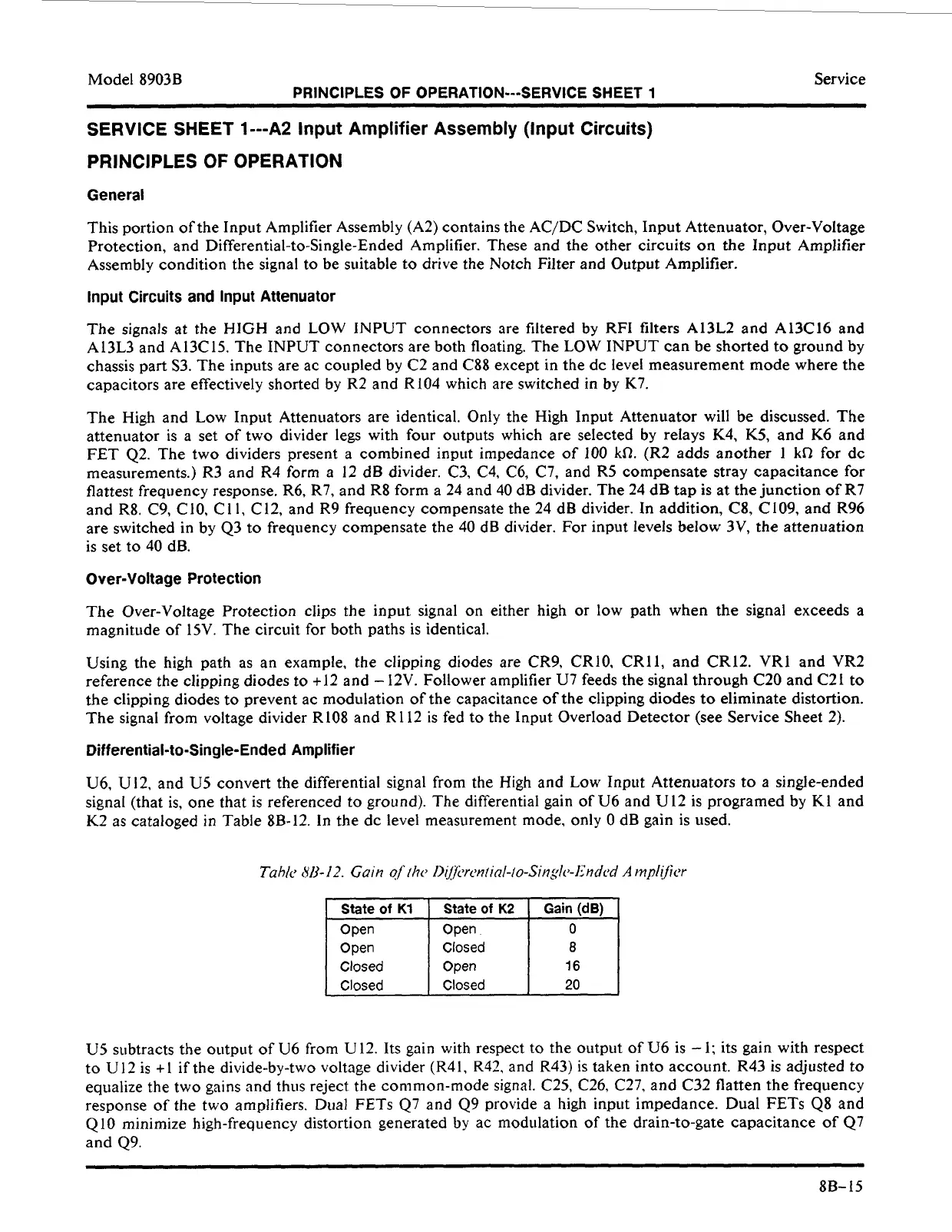
signal (that is, one that is referenced to ground). The differential gain of U6 and U12 is programed by K1 and
K2 as cataloged in Table 8B-12. In the dc level measurement mode, only
0
dB gain is used.
Closed
Closed Open
Closed Closed
U5
subtracts the output of
U6
from U12. Its gain with respect to the output
of
U6 is -1; its gain with respect
to U12 is
+1
if the divide-by-two voltage divider (R41, R42, and R43) is taken into account. R43 is adjusted to
equalize the two gains and thus reject the common-mode signal. C25, C26, C27, and C32 flatten the frequency
response
of
the two amplifiers. Dual FETs
47
and Q9 provide a high input impedance. Dual
FETs
Q8
and
Q 10 minimize high-frequency distortion generated by ac modulation
of
the drain-to-gate capacitance of 47
and Q9.
8B-15
 Loading...


