Model 8903B
Oscilloscope
I
Check
I
Special
1
Display
TROUBLESHOOTING---SERVICE SHEET
1
Level (TTL) at
U15
Pins
I
I
Service
0
dB
12
dB
24
dB
TROUBLESHOOTING
General
Function
(mVPP)
4,
16
17,
3
6, 14
1.11
8100
to 8900
L
H
H
1.8 2000
to
2200
H
L
H
1.5
500
to
560
H
H
L
Procedures for checking the Input Amplifier Assembly are given below. The circuits or points
to
check are
marked on the schematic diagram by
a
hexagon with
a
check mark and
a
number inside, for example,
a.
In
addition, any points outside the labeled circuit area that must be checked are
also
identified. Fixed signals are
shown on the schematic
also
inside
a
hexagon, for example,
<
+1.9
TO
+2.1
VDC
>.
Extend the board assembly
where necessary to make measurements. These procedures assume that the source is working properly.
Equipment
Oscilloscope
..............................
HP 1740A
Test Oscillator
............................
HP
3310A
Input Attenuator and AC/DC Switch Check
1.
On the Audio Analyzer, key in 41.0 SPCL to initialize the instrument.
Set
the INPUT switch
to
FLOAT and
the OUTPUT switch
to
ground. Key in AMPTD
3
V.
Connect the HIGH OUTPUT to the HIGH INPUT.
Connect a high-impedance, ac coupled
oscilloscope
to the gate of Q7A.
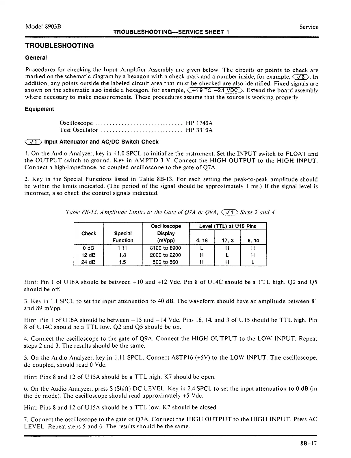
2.
Key in the Special Functions listed in Table
8B-13.
For each setting the peak-to-peak amplitude sho~tld
be within the limits indicated. (The period of the signal shoiild be approximately
I
ms.) If the signal level
is
incorrect, also check the control signals indicated.
Hint: Pin
1
of U I6A should be between
+10
and
+I2
Vdc. Pin 8 of U14C should be
a
TTL
high. 42 and
Q5
should be off.
3.
Key in
1.1
SPCL to set the input attenuation to
40
dB. The waveform shoiild have an amplitude between 81
and
89
mVpp.
Hint: Pin
I
of Ul6A should be between
-15
and
-
14 Vdc. Pins
16.
14, and
3
of U15 should be TTL high. Pin
8 of U14C should be a TTL low. Q2 and
Q5
should be
on.
4.
Connect the oscilloscope
to
the gate
of
Q9A. Connect the HIGH OUTPUT to the
LOW
INPUT. Repeat
steps
2
and 3. The results shoiild be the same.
5.
On the Audio Analyzer,
key
in
1.11
SPCL. Connect A8TPl6
(+5V)
to the
LOW
INPUT. The oscilloscope,
dc
coupled, should read
0
Vdc.
Hint: Pins
8
and
12
of
U15A should be a TTL high.
K7
should be open.
6.
On
the Audio Analyzer, press
S
(Shift)
DC
LEVEL. Key in 2.4 SPCL to set the inpiit attenuation to
0
dB (in
the dc mode). The oscilloscope should read approximately
+5
Vdc.
Hint: Pins
8
and
12
of U15A should be
a
TTL low. K7 should be closed.
7.
Connect the oscilloscope to the gate of Q7A. Connect the HlGH OUTPUT to the HlGH INPUT. Press AC
LEVEL. Repeat steps
5
and 6. The results should be the same.
8B- 17
 Loading...


