Model 8903B
Service
TROUBLESHOOTING---SERVICE SHEET
1
Over-Voltage Protection
Check
1.
On the Audio Analyzer, key in 41.0 SPCL to initialize the instrument. Set the INPUT switch to FLOAT. Key
in 1.11 SPCL
to
set the input amplifier gain to
0
dB.
2.
Set the test oscillator to
1
kHz and
level
to approximately
I
Vrms. Connect the output
to
the Audio Analyzer’s
HIGH INPUT.
3.
Connect a high-impedance, dc coupled oscilloscope to the gate of Q7A.
4. Short A7TP6
(RSI)
to A8TP16
(+5V)
to inhibit the
Input
Overload Flip-Flop. (See Service Sheet 12.)
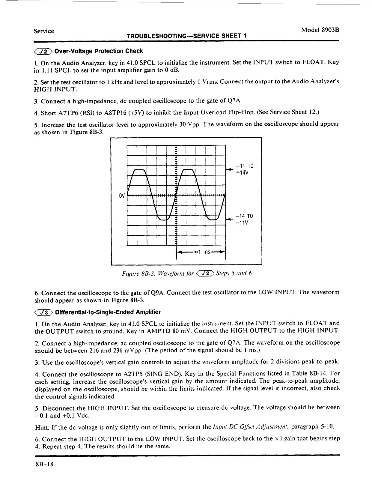
5.
Increase the test oscillator level to approximately 30
Vpp.
The waveform on the oscilloscope should appear
as shown in Figure 8B-3.
I
ov
+11
TO
+14V
-14
TO
-11v
6.
Connect the oscilloscope to the gate of
Q9A.
Connect the test oscillator to the LOW
INPUT.
The waveform
should appear as shown in Figure 8B-3.
a
Differential-to-Single-Ended Amplifier
1.
On the Audio Analyzer, key in 41.0 SPCL
to
initialize the instrument. Set the INPUT switch to FLOAT and
the OUTPUT switch to ground. Key in AMPTD 80 mV. Connect the
HIGH
OUTPUT to the
HlGH
INPUT.
2.
Connect
a
high-impedance,
ac
coupled oscilloscope to
the
gate
of
Q7A. The waveform
on
the oscilloscope
should be between 216 and 236 mVpp. (The period
of
the signal should be
1
ms.)
3.
Use the oscilloscope’s vertical gain controls to adjust the waveform amplitude
for
2 divisions peak-to-peak.
4.
Connect the oscilloscope to A2TP5 (SING
END).
Key in the Special Functions listed
in
Table 8B-14. For
each setting, increase the oscilloscope’s vertical gain by the amount indicated. The peak-to-peak amplitude,
displayed
on
the oscilloscope, shoiild be within the limits indicated.
If
the signal level is incorrect, also check
the control signals indicated.
5.
Disconnect the
HIGH
INPUT.
Set the oscilloscope to measure dc voltage. The voltage should be between
-0.1
and
+0.1
Vdc.
Hint:
If
the dc voltage
is
only slightly out
of
limits, perform
the
Inpi,(
DC
O/fier
Adjirsfrncnl,
paragraph 5-10.
6.
Connect the
HIGH
OUTPUT
to
the LOW INPUT. Set the oscilloscope back
to
the
x
1
gain that begins step
4. Repeat step
4.
The results should be the same.
8B-18
 Loading...


