Service
PRINCIPLES OF OPERATION---SERVICE SHEET
2
Model 8903B
SERVICE
SHEET 2---A2 Input Amplifier Assembly (Output Circuits)
PRINCIPLES
OF
OPERATION
General
This portion
of
the Input Amplifier Assembly
(A?)
contains a stage
of
programmable amplification, the Weight-
ing Bandpass and High-Pass Filters, and the lnput Range and Overload Detectors. The output of the assembly
drives the Notch Filter.
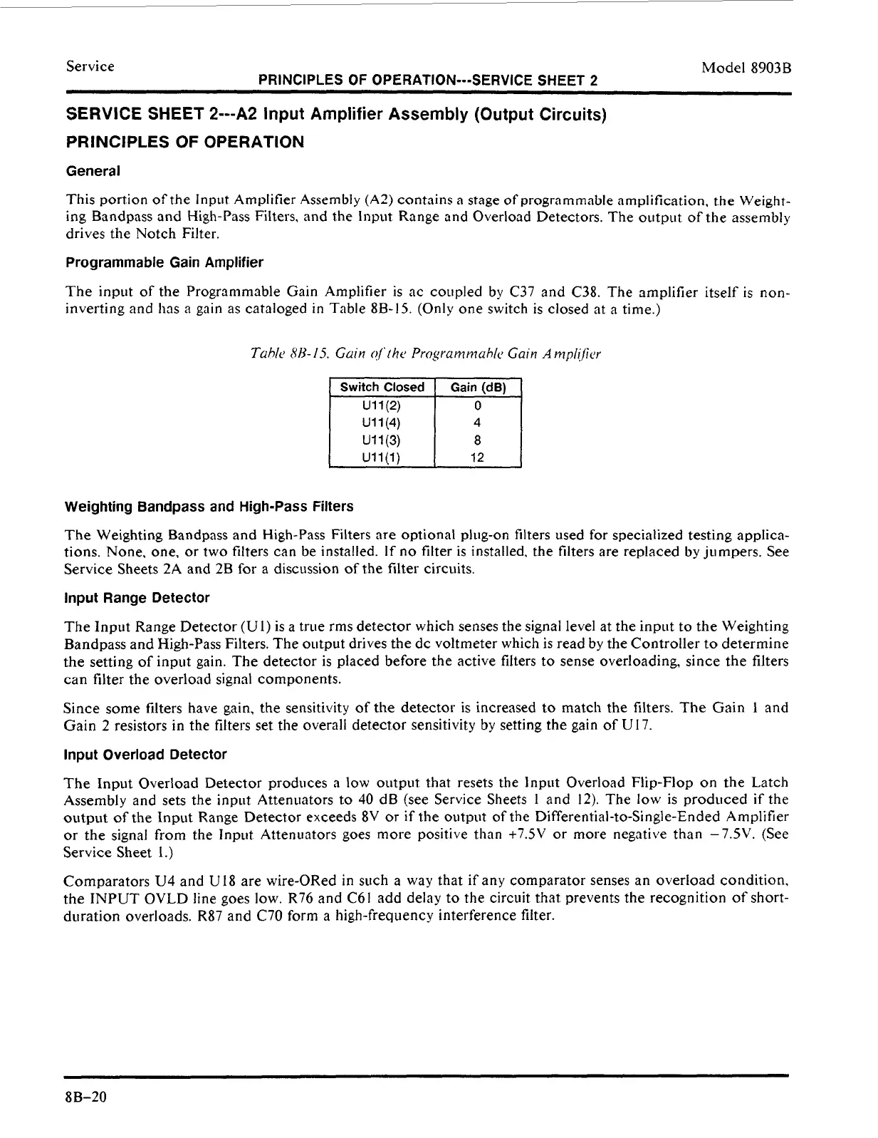
Programmable Gain Amplifier
The input
of
the Programmable Gain Amplifier is ac coupled by C37 and C38. The amplifier itself is non-
inverting and has
a
gain as cataloged
in
Table 8B-15. (Only one switch is closed at a time.)
u1
l(2)
u1
l(3)
u1
l(1)
12
U1
l(4)
Weighting Bandpass and High-Pass Filters
The Weighting Bandpass and High-Pass Filters are optional plug-on filters used for specialized testing applica-
tions. None, one, or two filters can be installed. If
no
filter is installed, the filters are replaced
by
jumpers. See
Service Sheets 2A and 2B for a discussion of the filter circuits.
Input Range Detector
The Input Range Detector
(U
I)
is a true rms detector which senses the signal level at the input to the Weighting
Bandpass and High-Pass Filters. The output drives the dc voltmeter which is read by the Controller
to
determine
the setting
of
input gain. The detector is placed before the active filters
to
sense overloading, since the filters
can filter the overload signal components.
Since some filters have gain, the sensitivity of the
detector
is increased
to
match the filters. The Gain
1
and
Gain
2
resistors in the filters
set
the overall detector sensitivity by setting the gain
of
U17.
Input Overload Detector
The Input Overload Detector produces a low output that resets the Input Overload Flip-Flop on the Latch
Assembly and sets the input Attenuators
to
40
dB (see Service Sheets
1
and
12).
The low is produced if the
output
of
the Input Range Detector exceeds 8V
or
if the output of the Differential-to-Single-Ended Amplifier
or the signal from the Jnpiit Attenuators goes more positive than
+7SV
or more negative than -7.5V. (See
Service Sheet
I
.)
Comparators
U4
and U18 are wire-ORed in such a way that if any comparator senses an overload condition,
the INPUT
OVLD
line goes low. R76 and
C61
add delay
to
the circuit that prevents the recognition of short-
duration overloads. R87 and C70 form a high-frequency interference filter.
8B-20
 Loading...


