Model 8903B
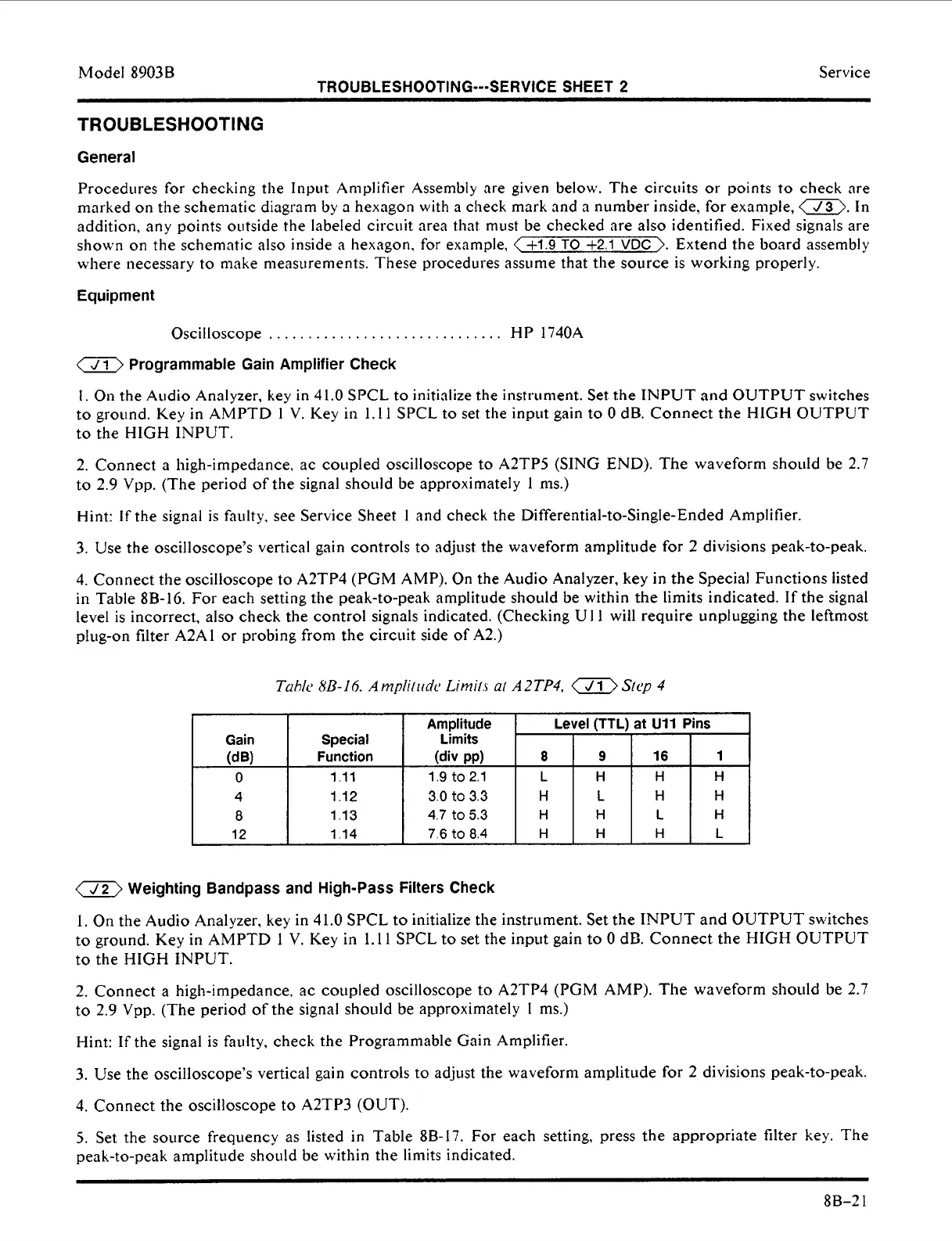
Gain Special
0
1.11
4 1.12
8
1.13
12 1.14
(dB) Function
TROUBLESHOOTING---SERVICE
SHEET
2
Amplitude
Limits
Level
(TTL)
at
U11
Pins
(div PPI
8
9
16
1
1.9
to
2.1
L H
H H
3.0
to
3.3
H
L
H H
4.7
to
5.3
H
H
L
H
7.6
to
8.4
H
H
H
L
Service
TROUBLESHOOTING
General
Procedures for checking the
Input
Amplifier Assembly are given below. The circuits
or
points
to
check
are
marked
on
the schematic diagram by
a
hexagon with
a
check mark and a number inside, for example,
a.
In
addition, any points outside
the
labeled circuit area that must be checked are also identified. Fixed signals are
shown
on
the schematic
also
inside
a
hexagon, for example,
<+1.9
TO
+2.1
VDC
>.
Extend the board assembly
where necessary
to
make measurements. These procediires assume that the soiirce is working properly.
Equipment
Oscilloscope
.
.
.
.
. . . . .
.
. .
.
. .
.
. . . . .
.
.
.
.
.
.
.
.
.
H P 1740A
a
Programmable Gain Amplifier Check
1.
On
the Audio Analyzer.
key
in
41.0
SPCL to initialize the instrument. Set the INPUT and OUTPUT switches
to
ground. Key in AMPTD
1
V. Key
in
1.11
SPCL
to set the input gain to
0
dB. Connect the HIGH OUTPUT
to
the HIGH INPUT.
2. Connect
a
high-impedance. ac coupled oscilloscope
to
A2TP5 (SING END). The waveform should be 2.7
to
2.9 Vpp. (The period of the signal shoiild be approximately
1
nis.)
Hint: If the signal is faulty, see Service Sheet
I
and check the
Differential-to-Single-Ended
Amplifier.
3.
Use the oscilloscope’s vertical gain controls
to
adjust the waveform amplitude for 2 divisions peak-to-peak.
4. Connect the oscilloscope to A2TP4 (PGM AMP). On the Audio Analyzer, key in the Special Functions listed
in Table 8B-16. For each setting the peak-to-peak amplitude should be within the limits indicated. If the signal
level is incorrect, also check the control signals indicated. (Checking U
I
1
will require unplugging the leftmost
plug-on filter A2AI or probing from the circuit side of A2.)
a
Weighting Bandpass and High-Pass Filters Check
1. On the Audio Analyzer,
key
in 41.0 SPCL to initialize the instrument. Set the INPUT and OUTPUT switches
to
ground. Key in AMPTD 1
V.
Key in 1.1 1 SPCL
to
set the input gain
to
0
dE. Connect the HIGH OUTPUT
to the HIGH INPUT.
2. Connect
a
high-impedance, ac coupled oscilloscope to A2TP4
(PGM
AMP). The waveform should be 2.7
to
2.9 Vpp. (The period of the signal should be approximately
I
ms.)
Hint: If the signal is faulty, check the Programmable Gain Amplifier.
3.
Use the oscilloscope’s vertical gain controls
to
adjust the waveform amplitude for 2 divisions peak-to-peak.
4.
Connect the oscilloscope to A2TP3 (OUT).
5.
Set the source frequency
as
listed in Table 8B-17.
For
each setting, press the appropriate filter
key.
The
peak-to-peak amplitude should be within the limits indicated.
8B-2
1
 Loading...


