Service Model 89038
TROUBLESHOOTING---SERVICE SHEET
2
Weighting Bandpass
or
High-Pass Filter
(Both
Off
or
None)
HIGH
PASS
400
Hz
CCITT WEIGHTING
CClR WEIGHTING
C-Message WEIGHTING
CCIR/ARM WEIGHTING
"A"
WEIGHTING
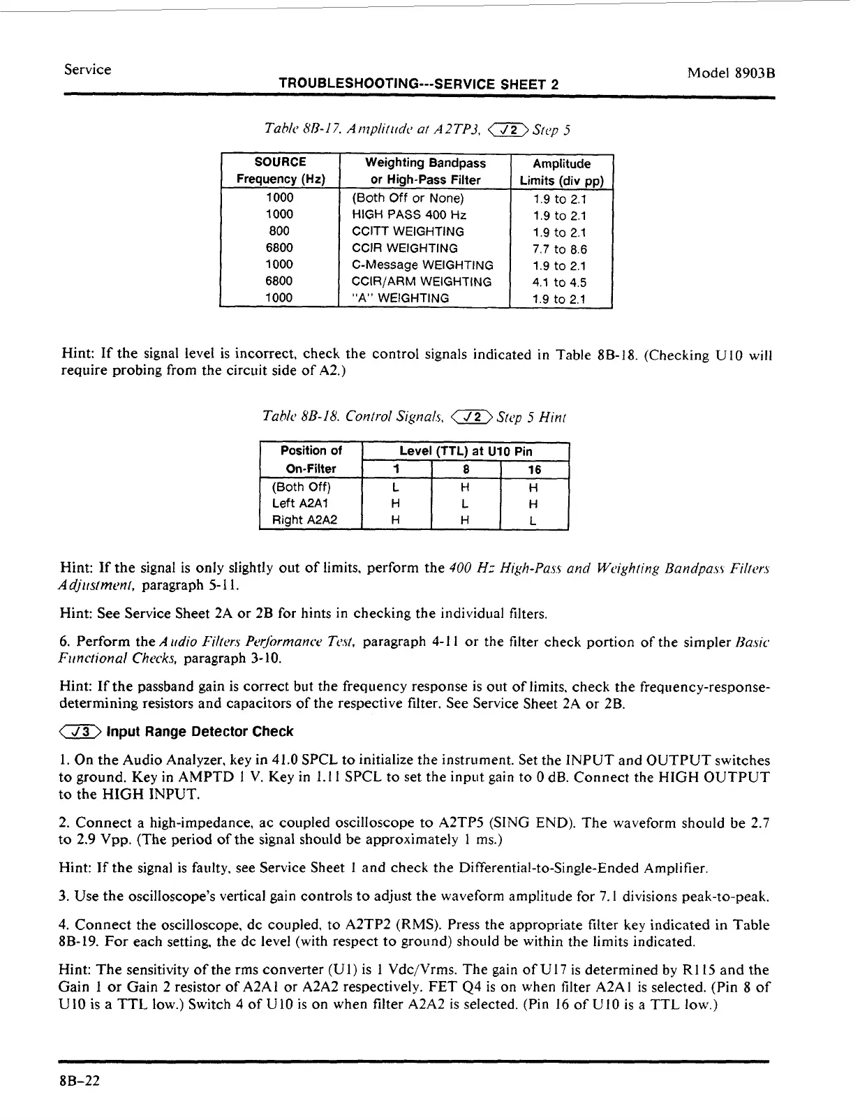
Tahlc
8/3-17.
Ati?plititdc
at
A2TP3,
Stcy
5
Amplitude
Limits (div pp)
1.9 to
2.1
1.9
to
2.1
1.9
to
2.1
7.7
to
8.6
1.9
to
2.1
4.1
to
4.5
1.9
to
2.1
6800
1000
6800
1000
On-Filter
..
1
I
8
I
16
-
Hint: If the signal
level
is incorrect, check the control signals indicated
in
Table 8B-18. (Checking
U10
will
require probing from the circuit side of A2.)
Left
A2A1
Right
A2A2
Tablo
8B-18.
Control
Signal.s,
a
Step
5
Hin,
H
L
H
H H
L
I
Position
of
I
Level (TTL) at U10 Pin
I
Hint: If the signal is only slightly out of limits, perform the
400
Hz High-Pass
and
Weighting
Bandpa.r.r
Filtcv-s
A
djiis/rnen/,
paragraph
5-
1
1.
Hint: See Service Sheet 2A
or
2B for hints
in
checking the individual filters.
6.
Perform the
A
iidio
Fi1tcr.s
Pt~rJiwrnanct~
Teul.
paragraph
4-1
1
or
the filter check portion
of
the simpler
Rasic.
Firnctional
Chccks,
paragraph 3-10.
Hint: If the passband gain is correct but the frequency response is out of limits,
check
the frequency-response-
determining resistors and capacitors of the respective filter. See Service Sheet 2A
or
2B.
a
Input
Range
Detector
Check
1.
On the Audio Analyzer, key in
41.0
SPCL to initialize the instriiment. Set the
INPUT
and OUTPUT switches
to ground. Key
in
AMPTD
1
V.
Key
in
1.1
1
SPCL to set the input gain to
0
dB. Connect the HIGH OUTPUT
to the HIGH INPUT.
2. Connect a high-impedance, ac coupled oscilloscope to A2TP5
(SING
END). The waveform should be 2.7
to
2.9 Vpp. (The period of the signal should be approximately
1
ms.)
Hint: If the signal is faulty. see Service Sheet
1
and check the Differential-to-Single-Ended Amplifier.
3.
Use the oscilloscope's vertical gain controls to adjust the waveform amplitude for 7.1 divisions peak-to-peak.
4.
Connect the oscilloscope, dc coupled, to A2TP2
(RMS).
Press the appropriate filter
key
indicated in Table
8B-19.
For
each setting, the dc level (with respect to ground) should be within the limits indicated.
Hint: The sensitivity of the rms converter
(UI)
is
1
Vdc/Vrms. The gain of
U17
is determined
by
R115
and the
Gain
1
or
Gain 2 resistor of A2A1
or
A2A2 respectively.
FET
44
is
on
when filter A2A1 is selected, (Pin
8
of
U10
is
a
TTL
low.) Switch
4
of
U10
is
on
when filter A2A2 is selected. (Pin
16
of
U10
is a TTL low.)
8B-22
 Loading...


