Model
89038
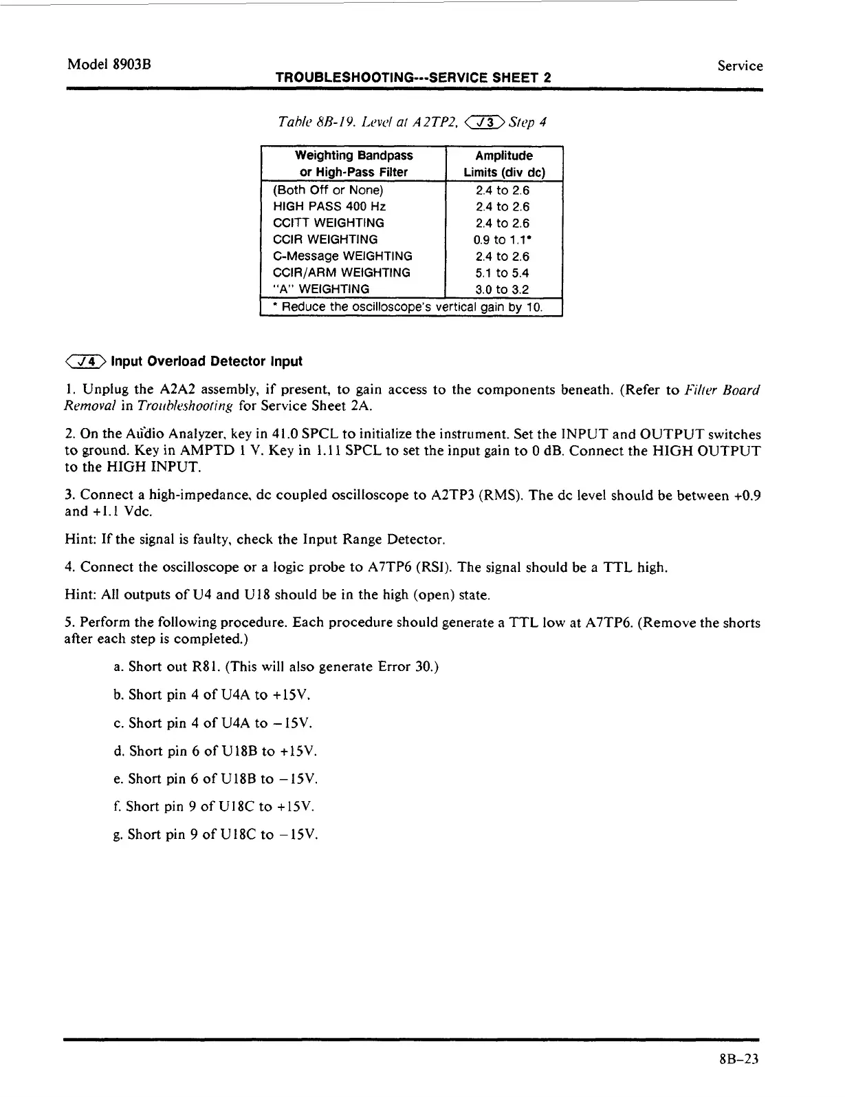
Weighting Bandpass
or
High-Pass Filter
(Both
Off
or
None)
HIGH PASS 400 Hz
CCITT WEIGHTING
CClR WEIGHTING
C-Message WEIGHTING
CCIR/ARM WEIGHTING
“A” WEIGHTING
TROUBLESHOOTING---SERVICE SHEET
2
Amplitude
Limits (div
dc)
2.4 to 2.6
2.4 to 2.6
2.4 to 2.6
0.9
to
1.1
2.4 to 2.6
5.1
to 5.4
3.0
to 3.2
Service
a
Input Overload Detector Input
1.
Unplug the A2A2 assembly, if present,
to
gain access to the components beneath. (Refer
to
Fii/t)r Hoard
Removal
in
Troiihkshoofing
for Service Sheet 2A.
2. On the A&iio Analyzer,
key
in 4
1.0
SPCL
to
initialize the instrument.
Set
the INPUT and OUTPUT switches
to
ground. Key
in
AMPTD
1
V. Key in 1.11 SPCL
to
set the input gain
to
0
dB.
Connect the HIGH OUTPUT
to
the HIGH INPUT.
3.
Connect a high-impedance, dc coupled oscilloscope
to
A2TP3
(RMS).
The
dc
level
should
be
between
+0.9
and +l.
I
Vdc.
Hint: If the signal is faulty, check the Input Range Detector.
4.
Connect the oscilloscope
or
a
logic
probe
to
A7TP6 (RSI). The signal should be
a
TTL high.
Hint: All outputs
of
U4 and U18 should be in the high (open) state.
5.
Perform the following procedure. Each procedure should generate a TTL low
at
A7TP6. (Remove the shorts
after each step is completed.)
a. Short out R81. (This will also generate Error 30.)
b.
Short pin
4
of
U4A
to
+15V,
c.
Short
pin
4
of U4A
to
-
15V.
d. Short pin
6
of U18B
to
+15V.
e.
Short pin
6
of
U18B
to
-
15V.
f. Short pin
9
of U 18C
to
+
15V.
g. Short pin
9
of
U
18C
to
-
15V.
8B-23