Model
8903B
TROUBLESHOOTING---SERVICE SHEETS 2A AND
2B
Service
Begin troubleshooting the Weighting Bandpass and High-Pass Filter Assemblies by performing the
Weighling
Hnnclparr
ond
High-forr
/.'il(crc
Chwk
on Service Sheet 2. If the passband gain is faulty. check the input offset
on the individual
ICs
on the filter assembly using the following guidelines. (Note that A2U9 is part of
a
filter
stage. It lies behind A2A1 but can be probed from the circuit side or. if desired, A2AI can be move to the
position
of
A2A2 while A2U9
is
cheched. See Service Sheet
2.)
a. Where bias voltages are shown on the schematic diagram, the
dc
voltage should be within the limits
shown.
b. Where bias voltages are not shown on the schematic diagram, the differential offset voltage at between
the input pins should be within
&I5
mVdc.
c. If the offset exceeds these limits. check the polarity of the output of the
IC.
If the polarity corresponds
with the polarity of the input offset, the
IC
is
probably good.
If
the filters appear
to
work properly except that the frequency response is out
of
limits, check the frequency
response of the individual filter stages against the following plots. An easy way to do this is as follows.
a.
Set the source to the desired frequency at 1V.
b. Set the LOW INPUT and
OUTPUT
switches to ground. Set IMPEDANCE
to
50R.
Connect the
HIGH
OUTPUT
to the HIGH INPUT.
c.
Connect an ac voltmeter to A2TP4 (PGM AMP). The voltmeter reading is a reference.
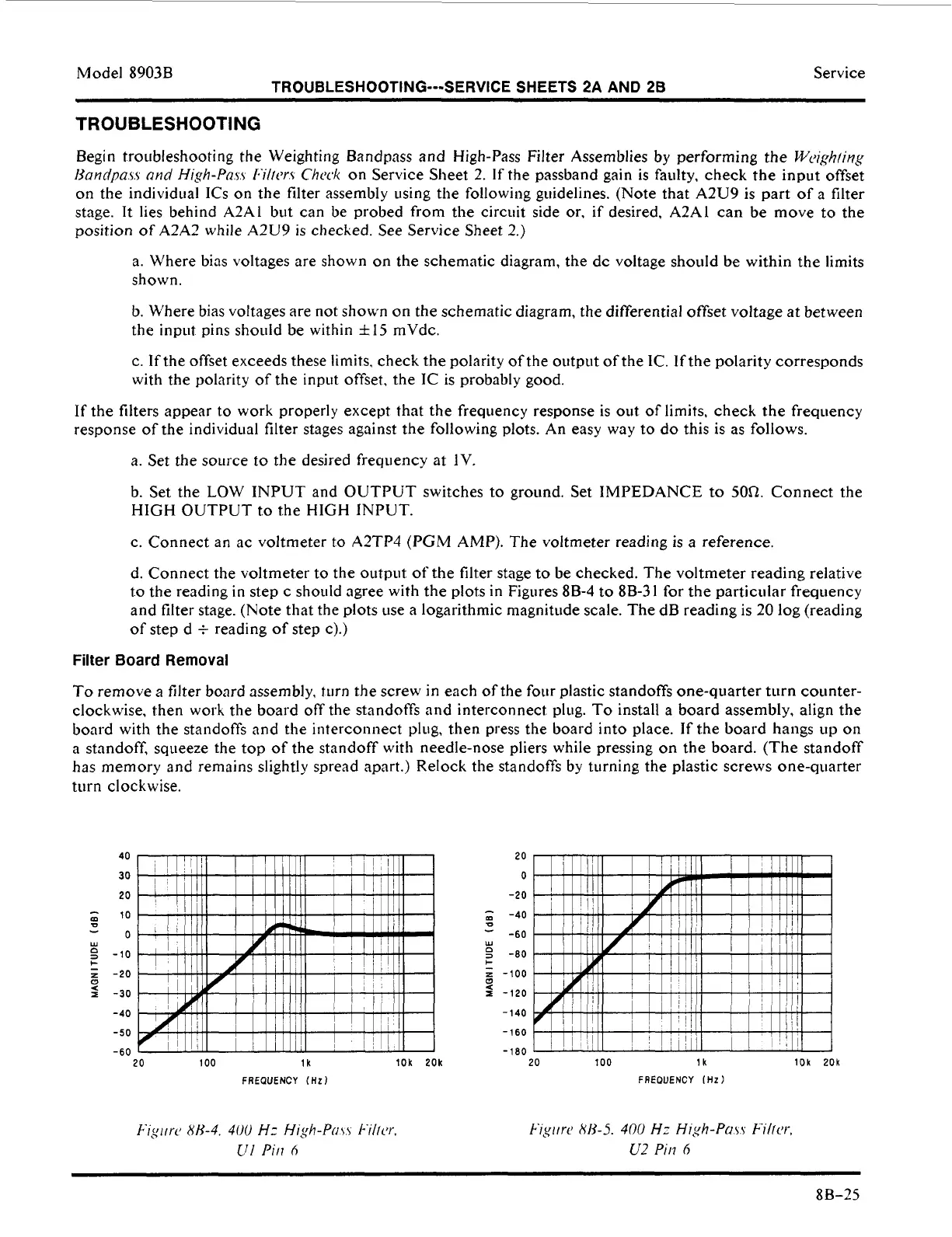
d. Connect
the
voltmeter to the output
of
the filter stage
to
be checked. The voltmeter reading relative
to
the
reading
in
step
c
should agree with the plots in Figures
8B-4
to
8B-31
for the particular frequency
and filter stage. (Note that the plots use
a
logarithmic magnitude scale. The dB reading is 20 log (reading
of step d
+
reading of step c).)
Filter
Board
Removal
To
remove a filter board assembly, turn the screw in each of the four plastic standoffs one-quarter turn counter-
clockwise, then worh the board
off
the standoffs and interconnect plug.
To
install a board assembly, align the
board with the standoffs and the interconnect plug, then press the board into place. If the board hangs up
on
a
standoff, squeeze the top of the standoff with needle-nose pliers while pressing
on
the board. (The standoff
has memory and remains slightly spread apart.) Relock the standoffs by turning the plastic screws one-quarter
turn clockwise.
20
100 lk 10k 20k
FREOUENCY
(Hz)
20
0
-20
,,,
-40
-60
n
3
-80
z
-100
-
0
-
W
+
a
2
-120
-140
-160
-180
20
100 lk
10k
20k
FREOUENCY
IHz)
~ ~~
88-25
 Loading...


