Model
8903B
Service
PRINCIPLES
OF
OPERATION---SERVICE SHEET
3
SERVICE SHEET
3---A3
Notch Filter Assembly (Notch-Generating Circuits)
PRINCIPLES
OF
OPERATION
General
This portion of the Notch Filter Assembly (A3) contains the basic notch-generating circuitry which includes
two integrators,
two
sum
amplifiers, and their control circuitry.
Integrators
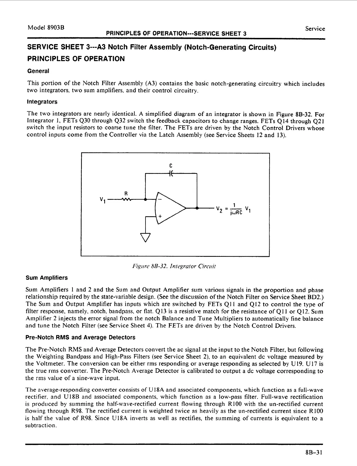
The
two
integrators are nearly identical. A simplified diagram of an integrator is shown in Figure
8B-32.
For
Integrator 1, FETs
430
through 432 switch the feedback capacitors
to
change ranges. FETs
414
through
421
switch the input resistors
to
coarse tune the filter. The FETs are driven by the Notch Control Drivers whose
control inputs come from the Controller via the Latch Assembly (see Service Sheets 12 and
13).
C
1
2
-
jwRC
v1
v
--
*
1:igiirc
8/1-32.
In
tcgrutor Circuit
Sum Amplifiers
Sum
Amplifiers
1
and 2 and the Sum and Output Amplifier sum various signals in the proportion and phase
relationship required
by
the state-variable design. (See the discussion of the Notch Filter
on
Service Sheet
BD2.)
The
Sum
and Output Amplifier has inputs which are switched by FETs Q11 and 412 to control the
type
of
filter response, namely, notch, bandpass, or flat.
413
is a resistive match for the resistance of
Q11
or
412.
Sum
Amplifier
2
injects the error signal from the notch Balance and Tune Multipliers
to
automatically fine balance
and tune the Notch Filter (see Service Sheet
4).
The
FETs
are driven by the Notch Control Drivers.
Pre-Notch
RMS
and
Average Detectors
The Pre-Notch
RMS
and Average Detectors convert the ac signal at the input to the Notch Filter, but following
the Weighting Bandpass and High-Pass Filters (see Service Sheet 2),
to
an equivalent dc voltage measured by
the Voltmeter. The conversion can be either rms responding or average responding
as
selected by
U19.
U17 is
the true rms converter. The Pre-Notch Average Detector is calibrated
to
output a dc voltage corresponding
to
the rms value of a sine-wave input.
The
average-responding converter consists
of
U
18A and associated components, which function as
a
full-wave
rectifier, and
U
18B and associated components, which function
as
a low-pass filter. Full-wave rectification
is produced by summing the half-wave-rectified current flowing through
RlOO
with the un-rectified current
flowing through R98. The rectified current is weighted twice
as
heavily as the un-rectified current since RlOO
is half the value of
R98.
Since
U18A
inverts as
well
as
rectifies, the summing of currents is equivalent
to
a
subtraction.
8B-3
1
 Loading...


