Model 8903B Service
TROUBLESHOOTING
General
Procedures for checking the Output Amplifier/Voltmeter Assembly are given below. The circuits or points to check
are marked on the schematic diagram by a hexagon with a check mark and a number inside, for example,
a.
In addition, any points outside the labeled circuit area that must be checked are also identified. Fixed signals are
shown on the schematic
also
inside a hexagon, for example,
0
Extend the board assembly where necessary to
make measurements. These procedures assume that the source
is
working properly.
Equipment
Digital Voltmeter
...........................
HP 3455A
Oscilloscope.
...............................
HP 1740A
(J1)
Output RMS/Average/Quasi-peak Detector General Check
1.
On the Audio Analyzer, key in 41.0 SPCL
to
initialize the instrument. Set the INPUT and OUTPUT switches
to ground. Key in AMPTD
3
V. Key in
1.11
SPCL to
set
the input gain to
0
dB.
Key in
3.1
SPCL
to
set the
output gain to
0
dB.
Connect the HIGH OUTPUT
to
the HIGH INPUT.
2. Connect a voltmeter to A4TP4 (AMP 4). Set the voltmeter to measure ac. Fine adjust the Audio Analyzer’s
SOURCE amplitude for 2.99 to 3.01
Vrms
on the voltmeter.
Hint: The amplitude
at
A4TP4 before adjustment should be between 2.85 and 3.15 Vrms.
If
the signal
is
faulty,
see Service Sheet
5
and check the Output Amplifier circuitry.
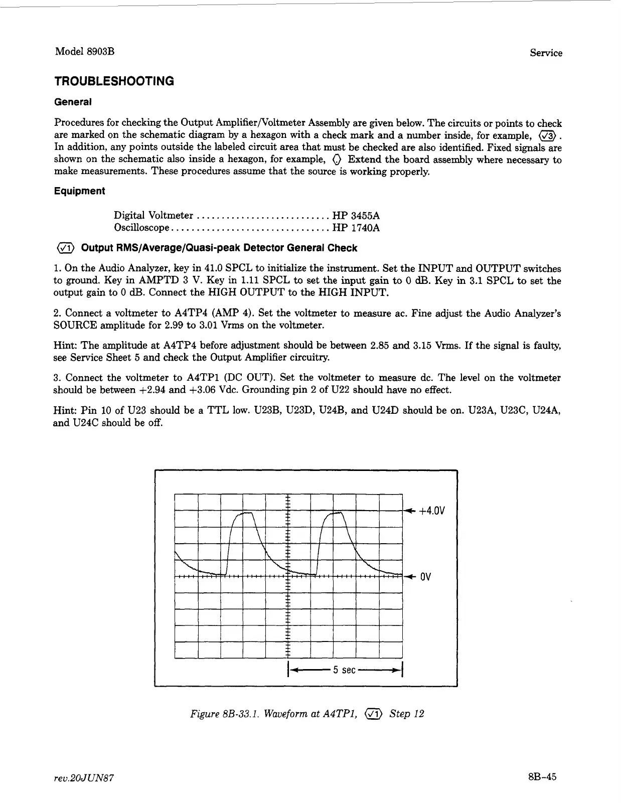
3. Connect the voltmeter to A4TPl (DC OUT). Set the voltmeter
to
measure dc. The level on the voltmeter
should be between +2.94 and +3.06 Vdc. Grounding pin 2 of U22 should have no effect.
Hint: Pin
10
of
U23 should be
a
TTL low. U23B, U23D, U24B, and U24D should be on. U23A, U23C, U24A,
and U24C should be
off.
+4
ov
.ov
Figure
8B-33.1.
Waveform at
A4TP1,
Step
12
rev.20JUN87
8B-45