Service
Model 8903B
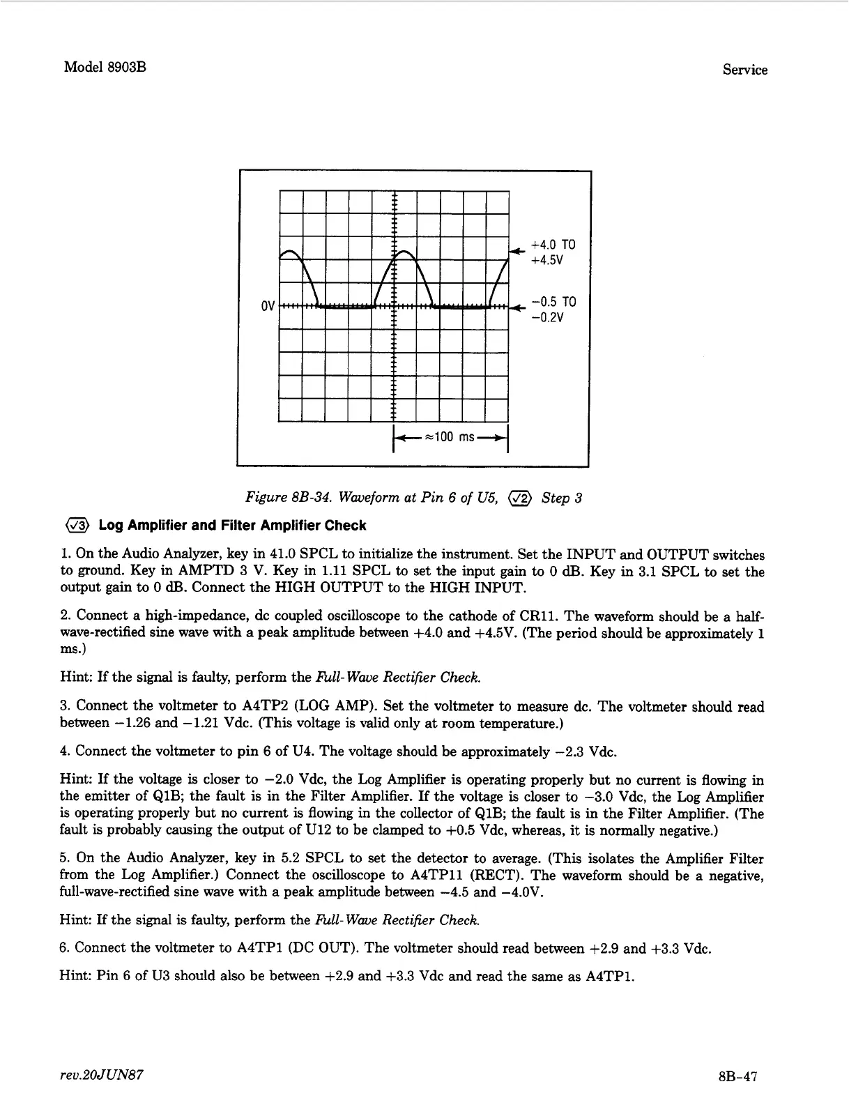
+4.0
TO
+4.5v
-0.5
TO
-0.2v
Figure
8B-34.
Waveform
ut
Pin
6
of
U5,
(J2)
Step
3
(J3)
Log
Amplifier
and
Filter Amplifier Check
1.
On the Audio Analyzer, key in 41.0 SPCL to initialize the instrument. Set the INPUT and OUTPUT switches
to ground. Key in AMPTD
3
V. Key in
1.11
SPCL to set the input gain to
0
dB.
Key in 3.1 SPCL
to
set the
output gain
to
0
dB.
Connect the HIGH OUTPUT
to
the HIGH INPUT.
2. Connect a high-impedance, dc coupled oscilloscope
to
the cathode of CR11. The waveform should be a half-
wave-rectified sine wave with
a
peak amplitude between +4.0 and +4.5V. (The period should be approximately
1
ms.)
Hint:
If
the signal
is
faulty, perform the
hll-
Wave Rectifier Check.
3. Connect the voltmeter
to
A4TP2
(LOG
AMP). Set the voltmeter
to
measure dc. The voltmeter should read
between -1.26 and -1.21 Vdc. (This voltage
is
valid only at room temperature.)
4. Connect the voltmeter to pin 6 of U4. The voltage should be approximately -2.3 Vdc.
Hint:
If
the voltage
is
closer to -2.0 Vdc, the Log Amplifier
is
operating properly but no current
is
flowing in
the emitter of Q1B; the fault is in the Filter Amplifier.
If
the voltage
is
closer to -3.0 Vdc, the Log Amplifier
is
operating properly but no current
is
flowing in the collector of Q1B; the fault
is
in the Filter Amplifier. (The
fault
is
probably causing the output of U12 to be clamped
to
+OS
Vdc, whereas,
it
is
normally negative.)
5.
On the Audio Analyzer, key in 5.2 SPCL to set the detector to average. (This isolates the Amplifier Filter
from the Log Amplifier.) Connect the oscilloscope to A4TP11 (RECT). The waveform should be a negative,
full-wave-rectified sine wave with
a
peak amplitude between -4.5 and -4.OV.
Hint:
If
the signal
is
faulty, perform the
hll-
Wave Rectifier Check.
6.
Connect the voltmeter to A4TP1 (DC OUT). The voltmeter should read between +2.9 and
+3.3
Vdc.
Hint: Pin
6
of U3 should also be between +2.9 and +3.3 Vdc and read the same as A4TP1.
reu.2OJUN87
8B-47