Service
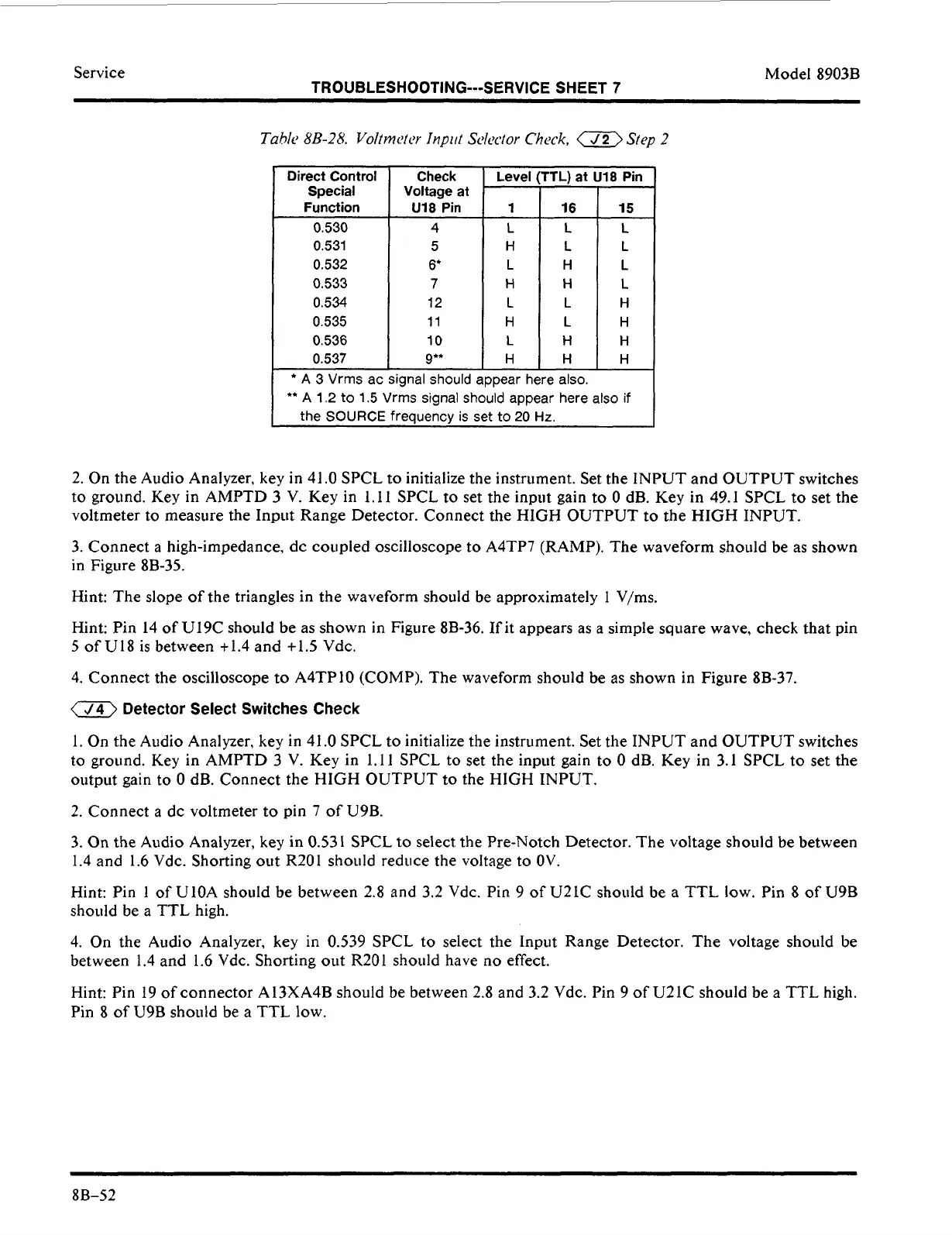
Direct Control
Special
Function
0.530
0.532
0.533
0.534
0.535
0.536
0.537
'
0.531
TROUBLESHOOTING---SERVICE SHEET
7
Check
Voltage at
U18
Pin
1
16
15
4
L
L
L
5
H
L
L
6'
L H
L
7
H
H
L
12
L L H
11
H
L
H
10
L
H
H
9**
H
H
H
Level
(TTL)
at
Ul8
Pin
Model 8903B
2. On the Audio Analyzer, key in 41
.O
SPCL to initialize the instrument. Set the INPUT and OUTPUT switches
to ground. Key in AMPTD
3
V. Key in 1.1
1
SPCL
to
set the input gain to
0
dB. Key in 49.1 SPCL to set the
voltmeter to measure the Input Range Detector. Connect the HIGH OUTPUT to the
HIGH
INPUT.
3. Connect
a
high-impedance, dc coupled oscilloscope to A4TP7 (RAMP). The waveform should be as shown
in Figure 8B-35.
Hint: The slope of the triangles in the waveform should be approximately
1
V/ms.
Hint: Pin 14
of
U19C should be as shown in Figure 8B-36. If it appears as a simple square wave, check that pin
5
of
U18 is between t1.4 and +1.5 Vdc.
4. Connect the oscilloscope to A4TPIO (COMP). The waveform should be as shown in Figure 8B-37.
a
Detector Select Switches Check
1.
On the Audio Analyzer, key
in
41.0 SPCL to initialize the instrument. Set the INPUT and OUTPUT switches
to ground. Key in AMPTD
3
V. Key in 1.11 SPCL to set the input gain to
0
dB. Key in
3.1
SPCL to set the
output gain to
0
dB. Connect the HIGH OUTPUT to the HIGH INPUT.
2. Connect a dc voltmeter to pin 7 of U9B.
3.
On
the Audio Analyzer,
key
in 0.53
1
SPCL
to
select the Pre-Notch Detector. The voltage should be between
1.4 and 1.6 Vdc. Shorting out R201 should reduce the voltage to
OV.
Hint: Pin
1
of UlOA should be between 2.8 and 3.2 Vdc. Pin 9 of U21C should be a TTL low. Pin
8
of
U9B
should be a TTL high.
4. On the Audio Analyzer,
key
in 0.539 SPCL to select the Input Range Detector. The voltage should be
between 1.4 and
1.6
Vdc. Shorting out R201 should have no effect.
Hint: Pin
19
of connector A13XA4B should be between 2.8 and 3.2 Vdc. Pin
9
of
U21C should be a TTL high.
Pin
8
of
U9B
should
be a TTL low.
88-52