a. Remove the display panel assembly.
b. Position the display panel assembly with the panel facing down.
IMPORTANT: Before placing the display panel assembly with the panel facing down, make sure
there are no foreign objects (tools, screws) on the work surface. Failure to follow this note can lead to
damage to the display panel assembly.
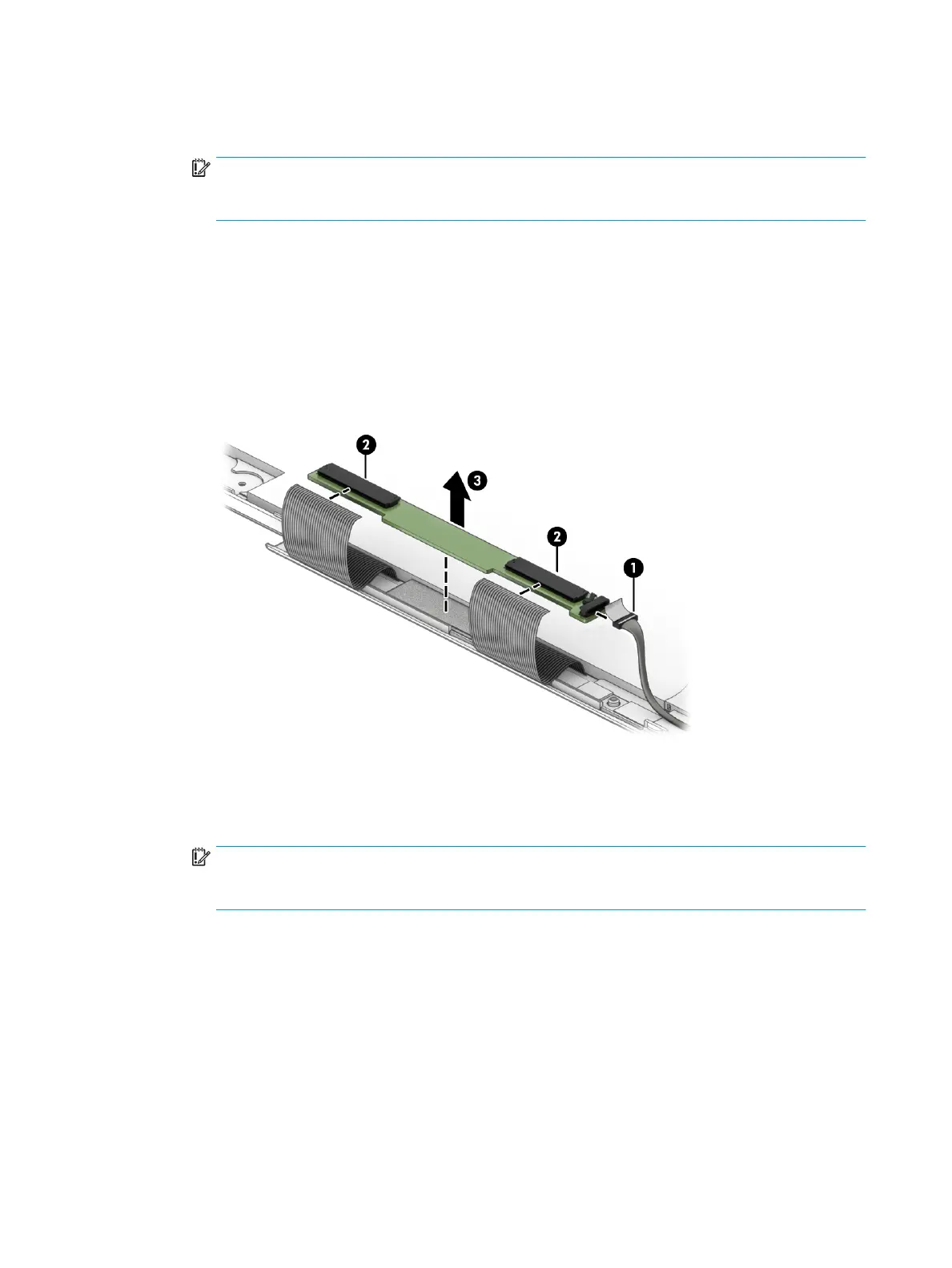
c. Disconnect the display panel cable (1) from the touch control board.
d. Release the ZIF connectors (2) to which the touch control board cables are connected, and then
disconnect the touch control board cables from the touch control board.
e. Detach the touch control board (3) from the display back cover. (The touch control board is attached
to the display back cover with double-sided adhesive.)
The touch control board is available using spare part numbers L76419-001 (for use only on computer
models equipped with a stylus) and L73657-001 (for use only on computer models not equipped
with a stylus).
13. If it is necessary to replace the G-sensor board:
a. Remove the display panel assembly.
b. Position the display panel assembly with the panel facing down.
IMPORTANT: Before placing the display panel assembly with the panel facing down, make sure
there are no foreign objects (tools, screws) on the work surface. Failure to follow this note can lead to
damage to the display panel assembly.
c. Disconnect the display panel cable (1) from the G-sensor board.
d. Release the support strip (2) that secures the G-sensor board to the display back cover.
32 Chapter 5 Removal and replacement procedures
 Loading...