The following list corresponds to the callouts shown in Figure 3-1.
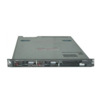
1. Utility node (a DL360 G4p is used in this example)
2. Administrative (Control) node (a DL360 G4p is used in this example)
3. PS/2 adapter
4. Eight-port console switch
5. TFT7600 rack-mount keyboard and monitor
6. PS/2 adapter cables from nodes connected to the console switch
7. Optional direct connections if there is no console switch
8. PS/2 adapter connections to the Administrative (Control) node
9. PS/2 adapter connections to the Utility node
10. TFT7600 serial connections to an eight-port console switch
64 Connecting and Powering Up the Core Cluster Components
 Loading...
