Location of connectors
DC controller PCA
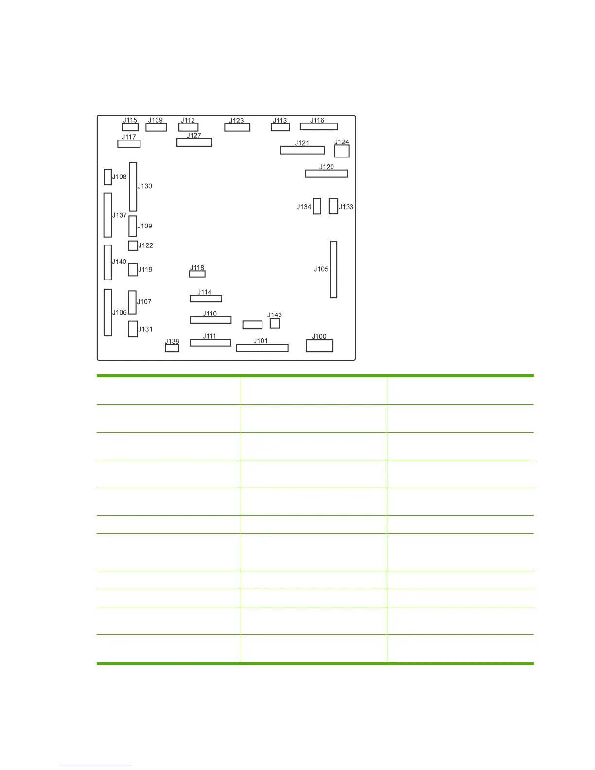
Figure 7-28 DC controller PCA
J126
Table 7-7 DC controller connectors
J100: 24 v from low-voltage power
supply (LVPS) and interlock
J114: HVPS lower J126: memory tag connector
J101: LVPS J115: fuser sensors J127: pre-exposure LEDs (rear), SR17,
SL1
J105: interconnect board (ICB) J116: HVPS upper J130: registration density (RD) sensors
(front and rear)
J106: 500-sheet feeder, developing
home position, laser motors
J117: fuser motor J131: pickup motor
J107: duplex sensor, tray 1 solenoid,
paper present sensor
J118: 5 v interlock J133: not used
J108: environmental sensor J119: LVPS fan J134: not used
J109: duplex clutch, overhead
transparency (OHT) in, top-of-page
sensor
J120: drum motor 1 and drum motor 2 J137: toner collection unit (TCU) full,
TCU motor, toner level detection
J110: YM laser J121: drum motor 3, drum position 1,2,3 J138: 24 v to HVPS lower
J111: CK laser J122: OHT out J139: fuser sensors
J112: pre-exposure LEDs (front) J123: pressure release, bin full, fuser
delivery
J140: lift motor, tray present, stack
surface
J113: 24 v to high-voltage power supply
(HVPS) upper
J124: 24 v to scanner-control board
(SCB)
J143: 24 v present from LVPS
412 Chapter 7 Solve problems ENWW
 Loading...
