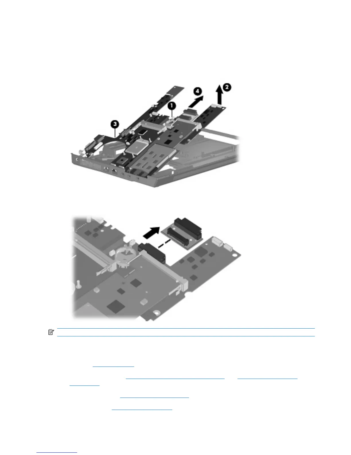
5. Use the right side of the system board (1) immediately behind the optical drive connector to lift the
right side of the system board (2) until the rear left corner of the system board (3) clears the base
enclosure.
6. Remove the system board (4) by pulling it away from the top cover at an angle until it clears the top
cover.
7.
If it is necessary to replace the optical drive connector board, pull the board away from the system
board until it disconnects from the system board.
NOTE: The optical drive connector board is available using spare part number 443820-001.
When replacing the system board, be sure that the following components are removed from the defective
system board and installed on the replacement system board:
●
SIM (see
SIM on page 49)
●
Memory modules (see
Expansion memory module on page 56 and Internal memory module
on page 66)
●
WLAN module (see
WLAN module on page 58)
●
RTC battery (see
RTC battery on page 67)
90 Chapter 4 Removal and replacement procedures ENWW