5–54 Maintenance and Service Guide
Removal and Replacement Procedures
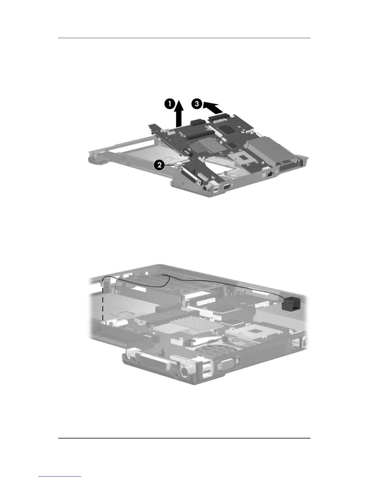
8. Use the optical drive connector to lift the system board up 1
until the power connector 2 is clear of the base enclosure.
9. Slide the system board to the left 3 at an angle and remove it.
Removing the System Board
10. If necessary, disconnect the RJ-11 connector module cable
from the system board and remove the RJ-11 connector
module and cable.
Removing the RJ-11 Connector Module and Cable
Reverse the above procedures to install the system board.
 Loading...