Do you have a question about the HP Compaq nx6125 and is the answer not in the manual?
Lists available processors, displays, storage, memory, OS, and connectivity options.
Steps to clear passwords and CMOS by removing the RTC battery.
Describes notebook power management features for battery life.
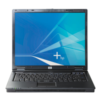
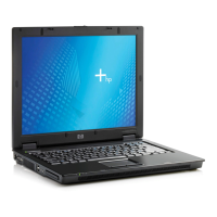
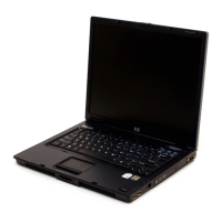
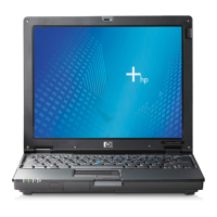
Identifies and describes external ports and indicators on the notebook's front, right, and left sides.
Overview of key parts and system board device connections.
Explains the ROM-based utility for system configuration and navigation.
Overview of diagnostic flowcharts for various system issues.
Instructions for updating HP software and system ROM via HP website.
Outlines methods for recovering system functionality, including Altiris Local Recovery and System Restore.
Shows where to find the notebook's serial and model numbers for service.
Illustrated breakdown of major notebook parts with corresponding spare part numbers.
Lists and illustrates plastic parts like covers, feet, and slot savers.
Lists and illustrates essential internal cables for various components.
Lists and illustrates hard drives and optical drives.
Lists spare parts not shown in illustrations, including AC adapters and screws.
Cross-references spare part numbers with their descriptions for easy lookup.
Lists specialized tools needed for notebook disassembly and reassembly.
Discusses general precautions for handling plastic parts and cables during service.
Provides precautions for handling fragile drives to prevent damage or data loss.
Explains the risks of ESD and how it affects electronic components.
Details grounding and packaging methods for ESD-sensitive equipment.
Outlines grounding and work area guidelines for static-safe servicing.
Describes proper grounding techniques using wrist straps, foot straps, and mats.
Instructions on reporting the notebook serial number for service requests.
Provides a step-by-step chart for component removal order.
Essential steps before starting component removal, including shutdown and battery removal.
Detailed procedure for removing and replacing the hard drive.
Instructions for replacing adhesive-backed rubber notebook feet.
Procedure for removing and replacing the Bluetooth wireless card.
Steps for accessing and replacing RAM modules.
Procedure for removing and replacing the optical drive.
Steps for removing and replacing the notebook's switch cover.
Procedure for removing and replacing the power button board assembly.
Detailed steps for removing and replacing the notebook keyboard.
Instructions for removing and replacing the notebook cooling fan.
Procedure for removing and replacing the processor heat sink.
Steps for removing and replacing the CPU.
Procedure for removing and replacing the button board assembly.
Instructions for removing and replacing wireless or other Mini PCI cards.
Detailed procedure for removing the entire display assembly.
Steps for removing and replacing the notebook's top cover.
Procedure for removing and replacing the TouchPad module.
Instructions for removing and replacing the Real-Time Clock battery.
Steps for removing and replacing the notebook speakers.
Detailed procedure for removing and replacing the main system board.
Instructions for removing and replacing the PC Card slot assembly.
Provides general specifications for notebook dimensions, weight, power, and environmental conditions.
Specifies dimensions, resolution, and other characteristics of the SXGA+WVA display.
Specifies dimensions, resolution, and other characteristics of the XGA display.
Lists technical specifications for various hard drive capacities.
Details specifications for the primary 6-cell Li-Ion battery.
Specifies technical details for the DVD-ROM drive.
Specifies technical details for the DVD/CD-RW combo drive.
Specifies technical details for the DVD±RW and CD-RW combo drive.
Specifies technical details for the CD-ROM drive.
Lists Direct Memory Access controller assignments.
Details hardware interrupt assignments for system functions.
Lists system input/output address mappings.
Provides a map of system memory addresses and their functions.
Pin assignments for the audio-out (headphone) jack.
Pin assignments for the audio-in (microphone) jack.
Pin assignments for USB ports.
Pin assignments for the S-Video-out connector.
Pin assignments for the external monitor connector.
Pin assignments for the RJ-11 modem jack.
Pin assignments for the RJ-45 network jack.
Details requirements for 3-conductor power cords.
Lists general specifications applicable to power cord sets worldwide.
Outlines country-specific agency approvals and notes for power cords.
Details Phillips PM2.5x6.0 screws, quantity, and usage locations.
Details Phillips PM3.0x5.0 screws, quantity, and usage locations.
Details Phillips PM1.5x3.0 screws, quantity, and usage locations.
Details Torx T8M2.5x9.0 screws, quantity, and usage locations.
Details Torx T8M2.5x4.0 screws, quantity, and usage locations.
Details Torx T8M2.5x7.0 screws, quantity, and usage locations.
Details Hex HM3.0x10.0 screw locks, quantity, and usage locations.
Details Phillips PM1.5x4.0 screws, quantity, and usage locations.
Discusses mercury content and disposal guidelines for display components.