8-191
Removal and Installation
HP Designjet 4500 Printer Series Service Manual
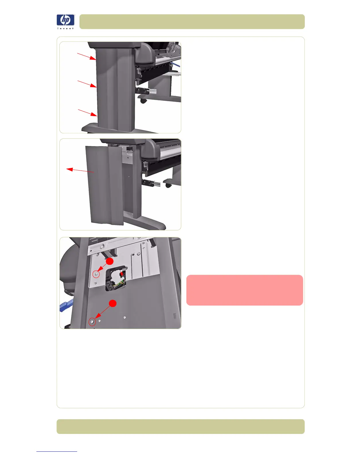
4. Apply pressure in the places shown to
unclip the Left Stand Cover.
5. Remove the Left Stand Cover.
6. For safety reasons make sure that the Load
Bearing Pin Screw (1) is installed in the
right leg of the printer. If this screw is not
installed the Roll 2 Module will crash to the
floor later in this procedure.
If the Load Bearing Pin Screw (1) is
not installed you can remove Pin
Screw (2) shown and install it in
the vacant (1) position.
1
2
 Loading...

