8-192
Removal and Installation
HP Designjet 4500 Printer Series Service Manual
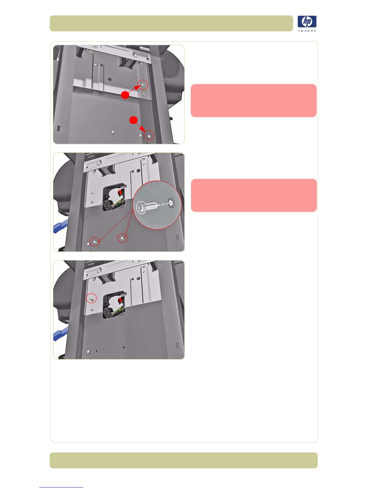
7. For safety reasons make sure that the Load
Bearing Pin Screw (1) is installed in the left
leg of the printer. If this screw is not
installed the Roll 2 Module will crash to the
floor later in this procedure.
If the Load Bearing Pin Screw (1) is
not installed, you can remove Pin
Screw (2) shown and install it in
the vacant (1) position.
8. Remove two T20 screws that secure the
right side of the Roll 2 Module to the
Printer.
The screws used to secure the
right side of the Roll 2 Module are
different from the screws that
secure the left side.
9. Remove a locking screw which locks the
right side of the Roll 2 Module in place.
1
2
 Loading...

