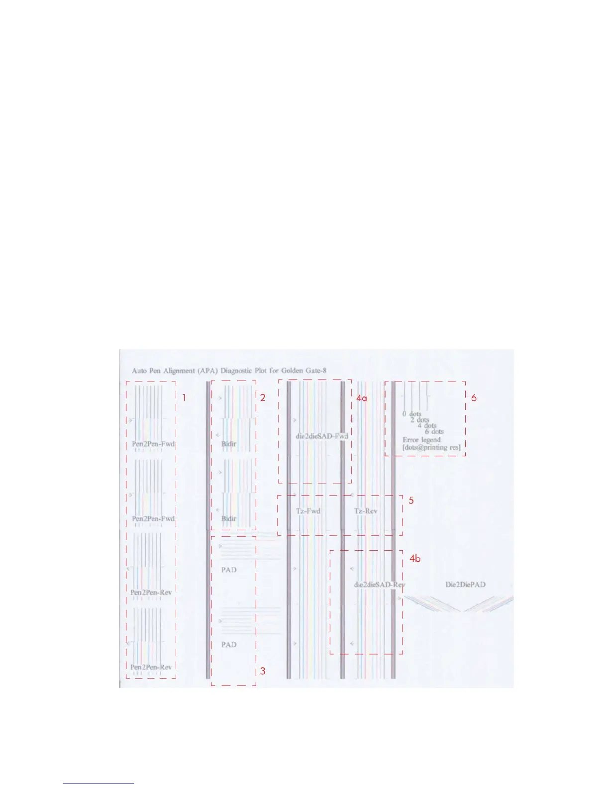
3. The printhead to printhead alignment in paper advance direction (PAD) is marked as number 3.
●
The top pattern is related to the front printhead (nearest to the user when doing the printhead
replacement).
●
The bottom pattern is related to the rear printhead (more far to the user when doing the
printhead replacement)
The area to check is the junction (marked with a “-”) of the black with the rest of colors.
4. The alignment in scan axis direction between both printhead of the same color is marked as 4a (in
forward direction die2dieSAD-Fwd) and 4b (in reverser direction die2dieSAD-Rev).
The area to check is the junction (marked with a “-”). The lines have to be continuous.
5. The ThetaZ of the printhead are checked in the area marked as 5. It checks in forward (Tz-Fwd)
and reverse directions (Tz-Rev).
The area to check is the junction (marked with a “-”). The lines have to be continuous.
6. The area marked as number 6 is a reference legend that shows junction misalignments of 2, 4
and 6 dots. The junction to check has to be below 4 in all cases. If the error is above 4 dots, then
realign the printheads.
In the next example, the Bidir is above this 4 dots and the unit should be realigned. The rest of the
pattern shows a right alignment.
What to see in the Dye Overlap Alignment.
ENWW
How to use the Image Quality Service Diagnostic Print
159
 Loading...