Removal and replacement procedures 44
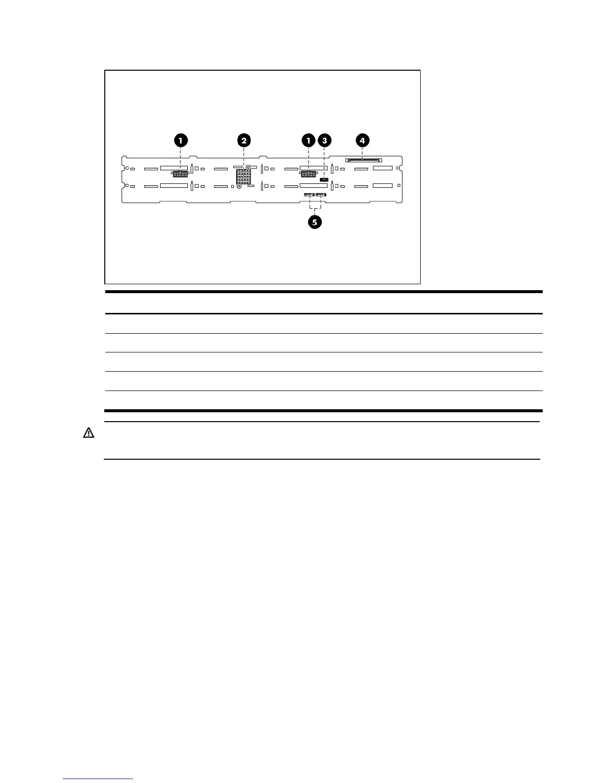
Figure 23 Backplane connectors of server with 12 HDD (solder side)
Item Description
1 10-pin power connector
2 SAS controller IC
3 LED signal cable connect to BPD
4 SAS connector
5 Cable connectors
WARNING: Ensure that the system is powered off and all power sources have been disconnected
from the server. Voltages are present at various locations within the server whenever an AC power
source is connected. This voltage is present even when the main power switch is in the off position.
To remove the backplane:
1. Remove all drives out of the drive bays.
Refer to the “Hard drives” sections in this chapter for detailed procedures.
 Loading...