CAUTION: When installing the display assembly, be sure that the wireless antenna cables are routed
and arranged properly.
Failure to properly route the antennas can result in degradation of the computer's wireless performance.
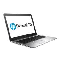
6. If you need to remove the display bezel, ex the top (1) of the bezel, the inside edges of the left and
right sides (2), and then the bottom (3) of the bezel until it disengages from the display enclosure..
NOTE: Make sure the hinges are not bent (see hinge position in following image) when you remove the
bezel.
7. Remove the display bezel (4).
The display bezel is available using spare part number 821158-001 for HP 755 and 821197-001 for HP
745.
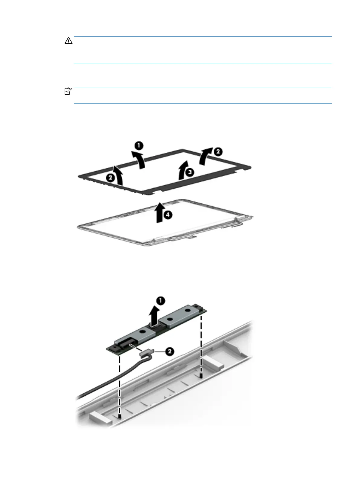
8. If it is necessary to replace the webcam or microphone module, gently pull the module away from the
double-sided tape on the display enclosure (1), and then disconnect the cable from the module (2).
The webcam module is available using spare part number 821676-001. The microphone module is
available using spare part number 821168-001.
Component replacement procedures 77
 Loading...