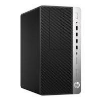
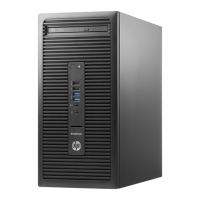
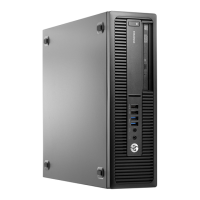
8. Pull the power switch out the front of the chassis (2), while routing the cable through the hole in
the chassis.
To install the power switch assembly, reverse the removal procedure.
NOTE: Be sure to correctly route the cables beneath the drive cage when reinstalling the assembly.
Proper cable routing prevents damage to the cables and allows the drive cage to close properly. See
Cable routing on page 57 for proper cable placement.
Power switch assembly
61
 Loading...
