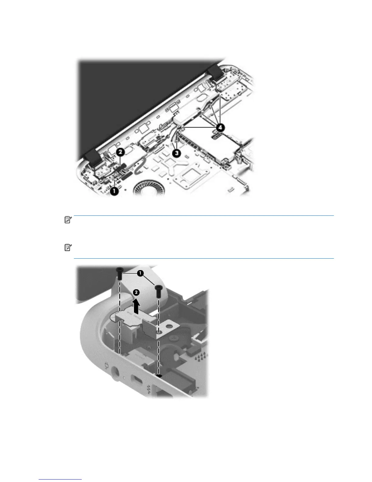
3. On the right side, disconnect the WLAN cable (3) and carefully remove the cable from the retaining tabs
(4).
4. Remove the power connector cover by removing the Phillips screw (1) and lifting the cover (2).
NOTE: The power connector cover has two screws, however, the screw on the left is removed during
the base enclosure and top cover removal process. Removing the cover is required for the display panel
removal.
NOTE: You will remove the power connector after you have removed the system board. This
procedure is to remove the power connector cover.
48 Chapter 6 Removal and replacement procedures for Authorized Service Provider parts
 Loading...