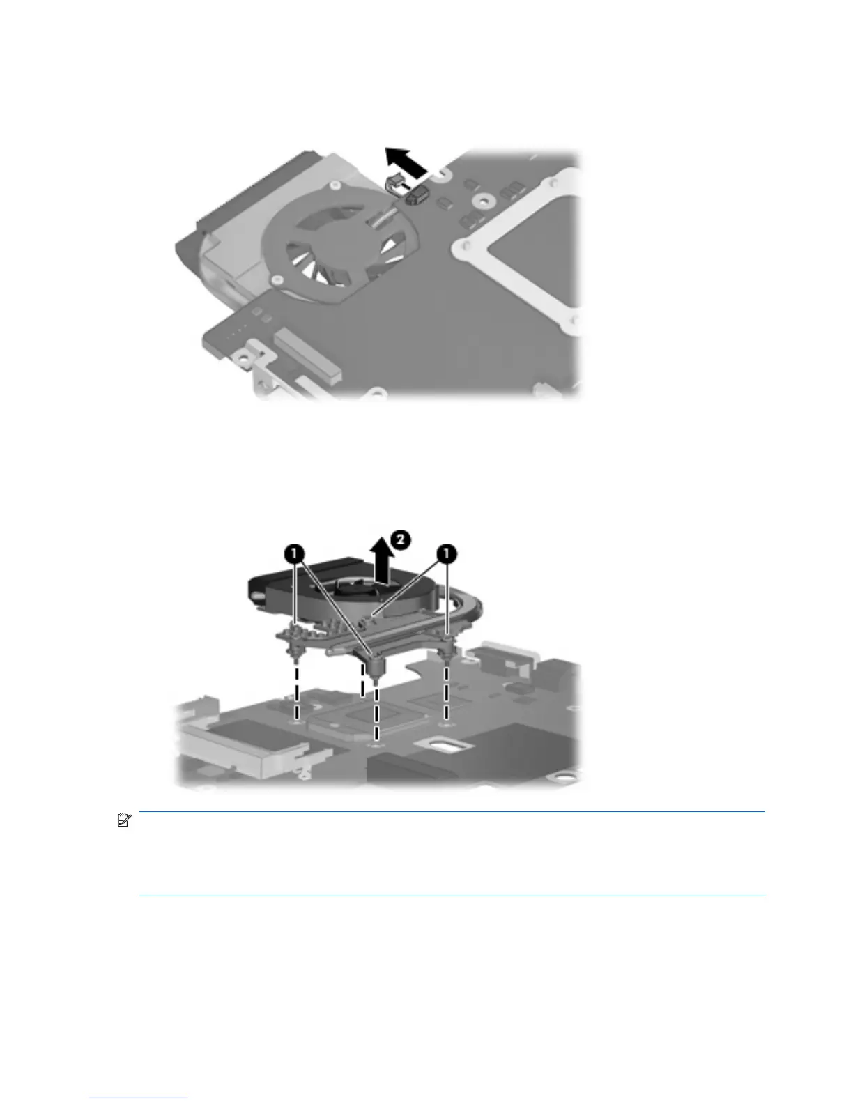
Remove the fan/heat sink assembly:
1. Disconnect the fan cable from the system board.
2. Turn the system board upside down, with the RJ-11 and RJ-45 jacks toward you.
3. Loosen the four Phillips PM2.0×10.0 captive screws (1) that secure the fan/heat sink assembly to
the system board.
4. Remove the fan/heat sink assembly (2) by lifting it straight up.
NOTE: The thermal material must be thoroughly cleaned from the surfaces of the fan/heat sink and
the system board components each time the fan/heat sink is removed. Thermal grease is located on
the section of the fan/heat sink (1) that services the processor (2). Thermal pads are located on the
section of the fan/heat sink (3) that services the Northbridge chip (4). Replacement thermal grease and
pads are included with all system board, fan/heat sink assembly, and processor spare part kits.
80 Chapter 4 Removal and replacement procedures