Do you have a question about the HP LE1851w and is the answer not in the manual?
Important safety information and warnings for servicing electronic equipment.
Caution regarding the use of an isolation transformer for servicing this unit.
Details of changes and revisions made to the service manual over time.
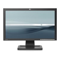
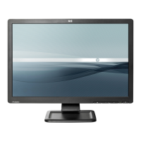
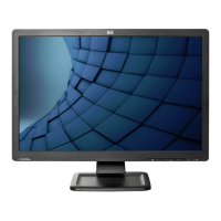
Technical specifications including screen size, resolution, and physical dimensions.
Operating conditions, power source, and consumption details for the monitor.
Description of the monitor's main components and their functional relationships.
Instructions for powering on and navigating the On-Screen Display (OSD) menu.
Explanation of the function of each physical button and LED indicator on the monitor.
Guidance on adjusting image quality parameters such as brightness and contrast.
Detailed list and explanation of available OSD menu settings for image and system control.
Information on the D-SUB connector pinout and supported display modes.
List of default video resolutions and their corresponding horizontal/vertical frequencies.
Key characteristics of the LCD panel, including pixel pitch and color depth.
Performance metrics such as color chromaticity, contrast ratio, and viewing angles.
Parameter guidelines for the CCFL inverter used in the backlight system.
Visual representation of the monitor's internal software operational flow.
Schematic detailing the electrical components and connections of the scalar board.
Detailed circuit diagram illustrating the main board's components and circuitry.
Diagram showing the physical layout and placement of components on the main board.
Diagram showing the physical layout and placement of components on the power board.
Diagram showing the physical layout and placement of components on the key board.
List of essential tools and equipment required for servicing the monitor.
Diagnostic procedures for common issues related to the main board, power board, and key board.
Procedure for calibrating color temperature and luminance using specialized equipment.
Instructions for disassembling the monitor, including stand, bezel, and internal components.
Visual representation of monitor parts with their corresponding part numbers for identification.
Comprehensive list of all parts used in the assembly, including part numbers and descriptions.
Comparison of specific parts used across different monitor model variations.
| 3D | No |
|---|---|
| Pixel pitch | 0.3 x 0.3 mm |
| Aspect ratio | 16:9 |
| Display diagonal | 18.5 \ |
| Display resolution | 1366 x 768 pixels |
| Viewing angle, vertical | 160 ° |
| Contrast ratio (typical) | 1000:1 |
| Display number of colors | - |
| Display brightness (typical) | 250 cd/m² |
| Supported graphics resolutions | 720 x 400, 832 x 624, 1024 x 768 (XGA), 1280 x 720 (HD 720), 1360 x 768 (WXGA), 640 x 480 (VGA), 800 x 600 (SVGA) |
| Package depth | 140 mm |
| Package width | 512 mm |
| Package height | 420 mm |
| Package weight | 5100 g |
| Product color | Black |
| Country of origin | China |
| Market positioning | Business |
| Plug and Play | Yes |
| LED indicators | Power |
| Tilt angle range | -5 - 25 ° |
| Panel mounting interface | 100 x 100 mm |
| Storage temperature (T-T) | 20 - 60 °C |
| Operating temperature (T-T) | 5 - 35 °C |
| Storage relative humidity (H-H) | 5 - 95 % |
| Operating relative humidity (H-H) | 20 - 80 % |
| AC input voltage | 100 - 240 V |
| AC input frequency | 50 - 60 Hz |
| Power consumption (off) | 1 W |
| Power consumption (standby) | 2 W |
| Power consumption (typical) | 31 W |
| Dimensions (W x D x H) (imperial) | 17.6 x 2.3 x 10.6 \ |
| DVI-D ports quantity | 0 |
| Depth (with stand) | 190 mm |
|---|---|
| Height (with stand) | 341 mm |
| Depth (without stand) | 58 mm |
| Width (without stand) | 446 mm |
| Height (without stand) | 269 mm |
| Weight (without stand) | 3800 g |