4. Remove one screw (callout 1) and the control panel assembly (callout 2).
Figure 1-63 Remove the control panel FFC (4 of 5)
1
2
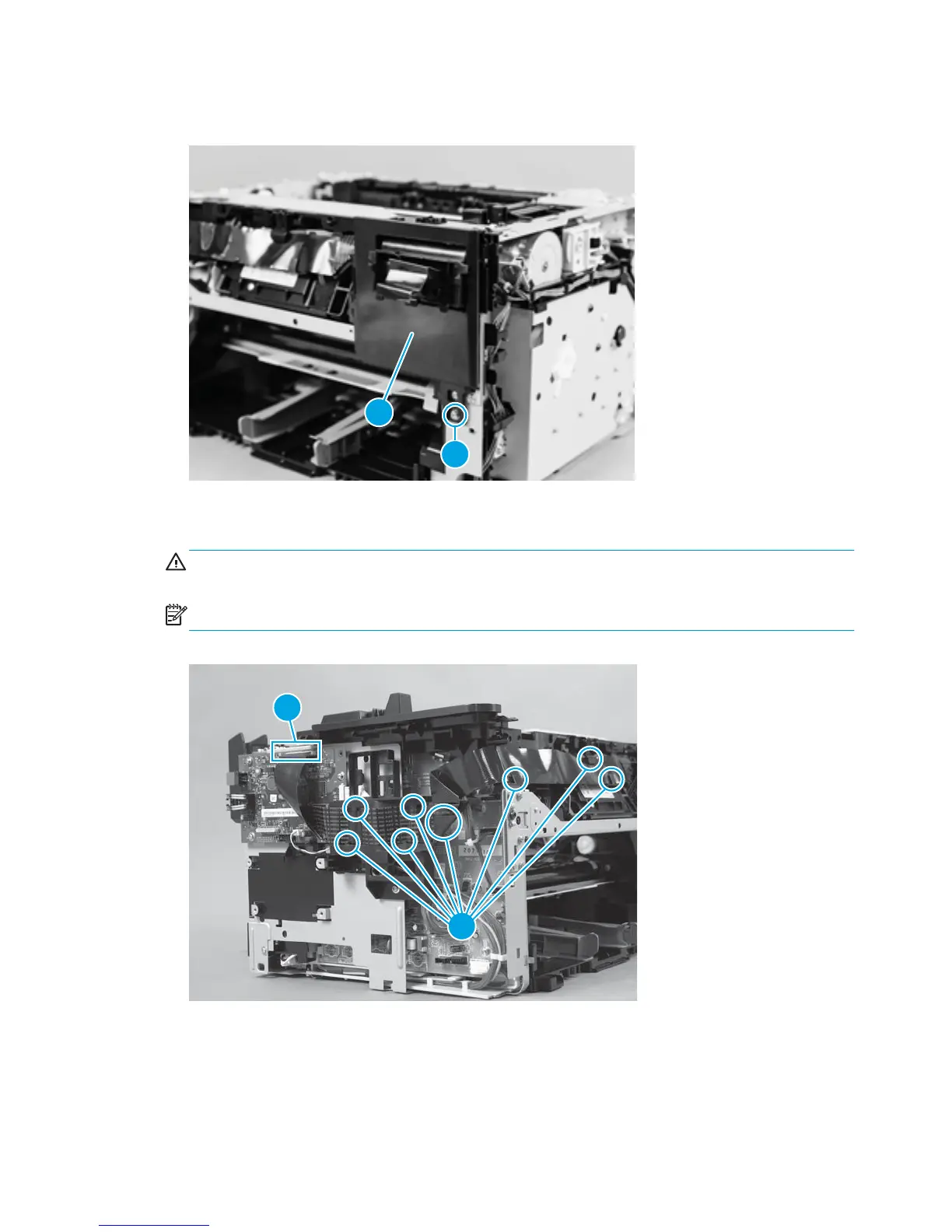
5. Disconnect one FFC (callout 1) from the formatter PCA, and then carefully remove the FFC from the
cable guides (callout 2).
CAUTION: Do not bend or fold the flat flexible cables (FFCs) during removal or installation. Do not
straighten pre-folds in the FFCs.
NOTE: The FFC guide might look slightly different from the figure, but the procedure is the same.
Figure 1-64 Remove the control panel FFC (5 of 5)
1
2
48 Chapter 1 Removal and replacement ENWW
 Loading...