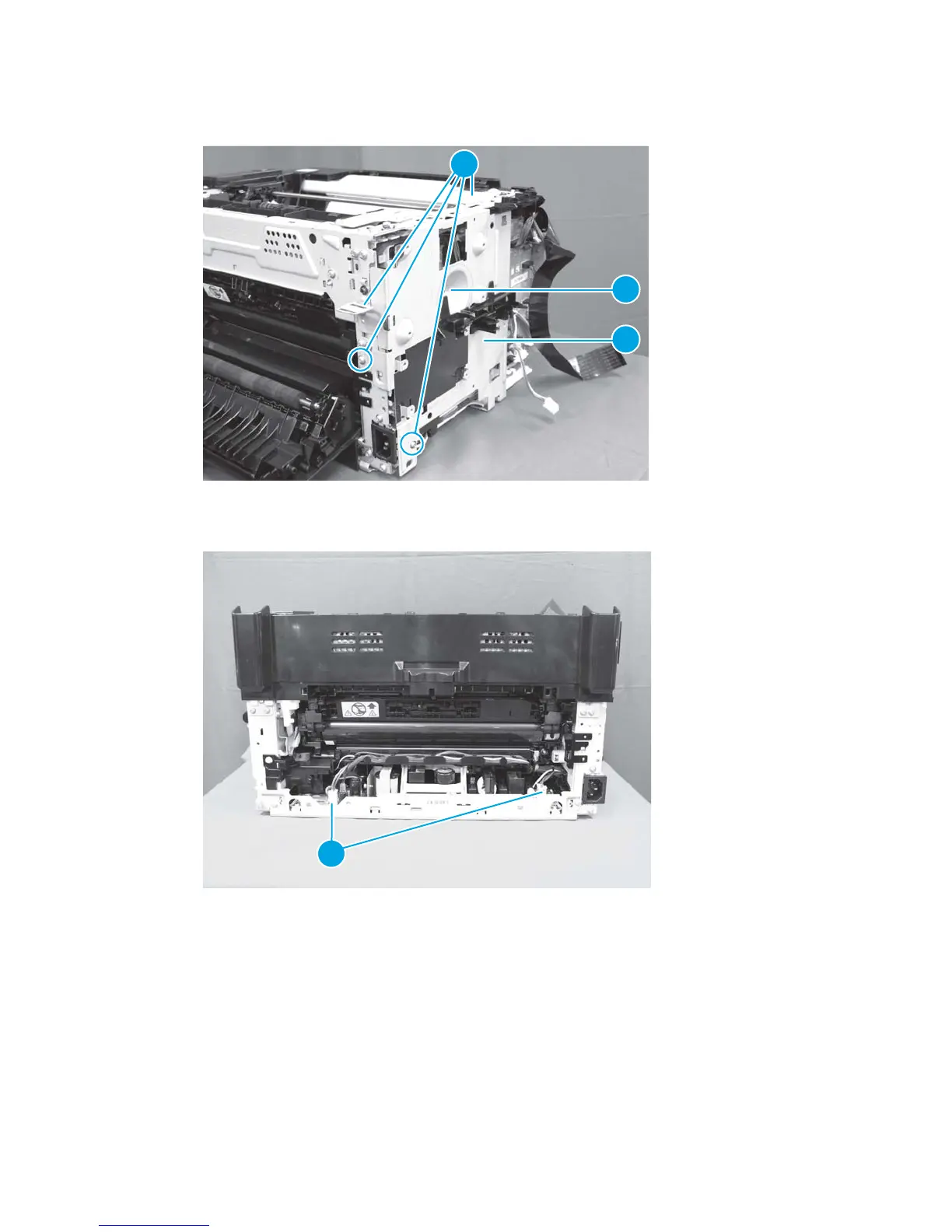
2. Remove four screws (callout 1), one black screw (callout 2), and the PCA plate (callout 3).
Figure 1-104 Remove the low-voltage power supply assembly and support frame (2 of 10)
1
2
3
3. Disconnect two connectors (callout 1).
Figure 1-105 Remove the low-voltage power supply assembly and support frame (3 of 10)
1
ENWW Removal and replacement procedures 73
 Loading...