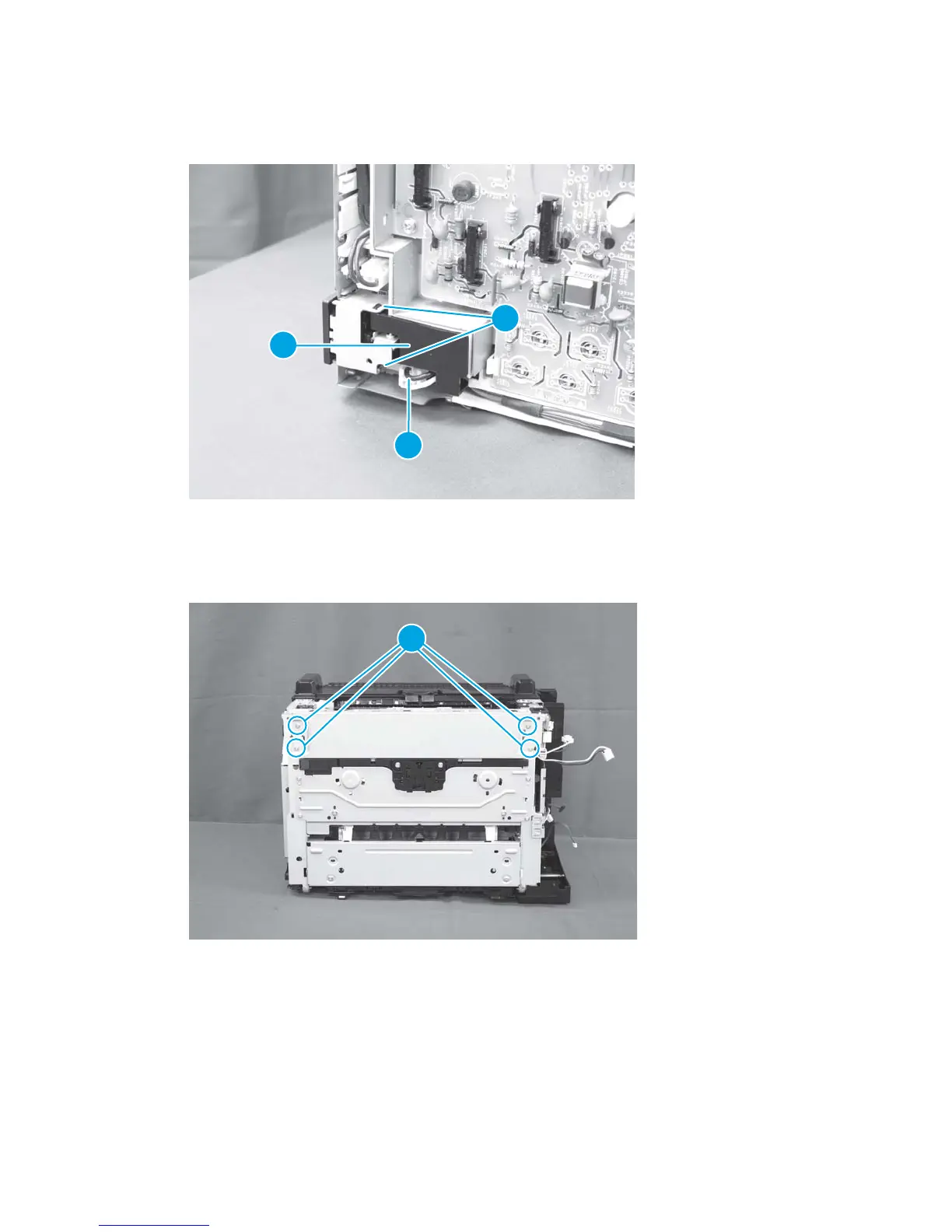
4. Disconnect one connector (callout 1), and then release two tabs (callout 2) and remove the core holder
(callout 3).
Figure 1-106 Remove the low-voltage power supply assembly and support frame (4 of 10)
2
1
3
5. Place the product rear-side up
6. Remove four screws (callout 1).
Figure 1-107 Remove the low-voltage power supply assembly and support frame (5 of 10)
1
7. Return the product to the upright position.
74 Chapter 1 Removal and replacement ENWW
 Loading...