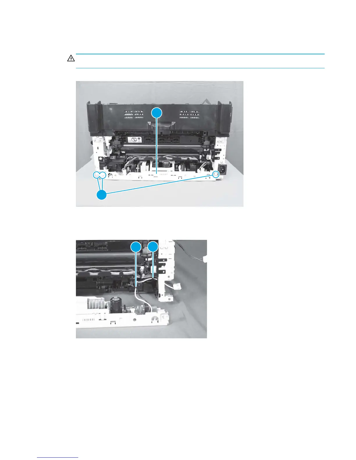
8. Remove three screws (callout 1), and then separate the low-voltage power supply assembly (callout 2)
from the product.
CAUTION: Do not attempt to completely remove the low-voltage power supply. The power supply is
still connected to the product by three internal connectors.
Figure 1-108 Remove the low-voltage power supply assembly and support frame (6 of 10)
1
2
9. Release the cables (callout 2) from the cable guide (callout 1), and then pull the wire harness through
the hole in the chassis.
Figure 1-109 Remove the low-voltage power supply assembly and support frame (7 of 10)
1
2
ENWW Removal and replacement procedures 75
 Loading...