Do you have a question about the HP Mini-in-One 24 and is the answer not in the manual?
This guide provides information about spare parts, removal and replacement of parts, diagnostic tests, problem troubleshooting, and more.
Read cautions and notes to minimize risk of personal injury. Proper service methods are important for safe operation.
Repair by professional technicians. End users should not perform procedures. Adherence to procedures and precautions is essential.
Details RoHS compliance requirements for products sold in the EU and other countries, including original and replacement parts.
This manual contains general information and describes two levels of service: cosmetic/alignment and circuit board/parts replacement.
Information on where to find firmware updates for the monitor on the HP support website.
Procedure to perform an AC leakage current check on exposed metallic parts to ensure safety before returning the product.
Details the monitor's features, including screen size, resolution, panel type, viewing angles, and adjustability.
Identifies and describes components on the front of the monitor, such as microphones, webcam, and power button.
Identifies and describes components on the sides of the monitor, including headset jack and USB 3.1 Gen1 ports.
Identifies and describes components on the rear of the monitor, including security slot, USB ports, and various connectors.
Details the location of the serial and product numbers on a barcode label on the bottom edge of the display head.
Provides an illustration and table identifying the monitor's major components by item number and description.
Lists EU distributors for connectors and provides part numbers for DisplayPort, USB, DC jack, and USB-C connectors.
Details steps to prepare for disassembly, including reading safety info, cleaning area, and gathering equipment.
Provides steps for removing the RC, starting with unscrewing the rear case and splitting the sides apart.
Details removing Mylar, screws, IO shielding, and small boards from the rear cover.
Outlines steps to remove the webcam module from the middle frame and the PCBA by releasing screws on the scaler board.
Describes removing speakers by releasing support brackets and removing the chassis, middle frame, and gasket.
Lists connector types and their general locations on the main and IO boards.
Shows images and identifies locations of connectors on the Main Board.
Shows images and identifies locations of connectors on the USB Side Board and Audio Board.
Provides steps for repairing the DP connector (CN5) using a hot air gun and soldering iron.
Details the repair process for the DC jack connector (CN1) using desoldering and soldering techniques.
Explains the repair of the USB upstream connector (P1) by desoldering and soldering a new component.
Covers repair of multiple USB connectors on the PCB, including desoldering, removal, and soldering.
Details the repair of the USB-C connector (P1) by heating the PCB, removing, and soldering a new component.
Outlines the repair procedure for the headphone connector (CN2) by heating the PCB and soldering a new component.
Describes tests for USB-C, DP, Audio, and USB ports to confirm correct operation after repair.
Lists common problems, their possible causes (e.g., power cord disconnected, display off), and recommended solutions.
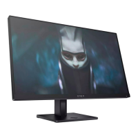
The HP Mini-in-One 24 model is a versatile display designed for integration with HP Desktop Mini PCs, offering a comprehensive solution for various computing environments. This device serves as a monitor and a docking station, providing a streamlined setup for users.
The primary function of the HP Mini-in-One 24 is to act as a display for a connected computer, specifically designed to house and integrate an HP Desktop Mini PC within its rear compartment. This integration allows for a single power-on experience for both the display and the Mini PC, simplifying operation and reducing cable clutter. The monitor supports a 35W or 65W HP Desktop Mini, creating a fully enclosed and compact workstation.
Beyond its display capabilities, the device functions as a connectivity hub. It features a USB Type-C connector for interfacing with an HP Desktop Mini, enabling data transfer and potentially power delivery. Additionally, it includes multiple USB 3.1 Gen1 ports (four on the rear and two on the side) for connecting various USB devices, an audio-out (headset) jack on the side for personal audio, and a USB Type-B upstream port to connect the display's USB hub to a source device. A DisplayPort video input is also available for connecting other video sources.
The integrated 1080p HD webcam with dual-array microphones allows for video conferencing and communication. The monitor also incorporates 2.5W stereo internal speakers for audio output. For security, a security cable slot is provided on the rear for an optional security cable.
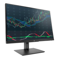
The HP Mini-in-One 24 offers a range of features designed to enhance user experience and adaptability. The display boasts a 60.5 cm (23.8-inch) diagonal viewable screen area with a 1920 × 1080 resolution, providing clear and crisp visuals. It also supports lower resolutions with full-screen capability. The nonglare panel with an LED backlight ensures comfortable viewing in various lighting conditions, while wide viewing angles allow for clear visibility from different sitting or standing positions.
Ergonomic adjustments are a key aspect of its design, with tilt, swivel, height, and pivot adjustment capabilities, enabling users to customize the display's position for optimal comfort and productivity. The removable stand offers flexibility for alternative mounting solutions, such as attaching the display to a wall mount device or swing arm using its VESA® mounting capability.
User interaction is facilitated through an intuitive on-screen display (OSD) menu, available in several languages, for easy setup and screen optimization. The OSD allows for adjustments such as brightness and color settings. Dedicated buttons on the rear of the monitor provide quick access to OSD functions, including a back button to exit or return to previous menu levels, plus and minus buttons for navigation and adjustment, and a Menu/OK button to open the OSD or select items. A master power switch on the rear allows for turning off all power to the display.
The monitor supports Plug and Play functionality, simplifying setup with compatible operating systems. It also features a Power Saver mode to meet requirements for reduced power consumption, contributing to energy efficiency. The integrated webcam includes a physical shutter for privacy, allowing users to open or close the webcam as needed.
The HP Mini-in-One 24 is designed with serviceability in mind, providing detailed procedures for maintenance and repair. The device is categorized into two levels of service: Level 1 for cosmetic/appearance/alignment service and Level 2 for circuit board or standard parts replacement. This structured approach ensures that repairs can be performed efficiently.
The service guide emphasizes important safety information and precautions, stressing that only trained service personnel familiar with the product should perform maintenance. It highlights the necessity of disconnecting the power cord before opening the monitor to prevent component damage and advises on following ESD safety procedures when handling electrical components.
For component replacement, the guide provides an illustrated parts catalog, detailing major components such as the mid-frame, deco bezel, panels, VESA mount, main chassis, scalar board, speakers, PCB brackets, IO shielding, bucket, vent cover, VESA cover, webcam module, side USB PCBA, and function PCBA. It also includes instructions on how to order spare parts, specifying distributors for various connectors and providing links to HP's part store for cables and other components.
Detailed removal and replacement procedures are outlined for various parts, starting with preparation for disassembly, which includes cleaning the work area, identifying the disassembly area, and ensuring the availability of necessary tools like press fixtures, screwdrivers, knives, gloves, cleaning cloths, ESD protection, and a scraper bar. Specific steps are provided for removing the rear case, splitting the middle frame, removing the IO shielding, small boards, webcam module, die casting, cables, and the PCBA. Instructions also cover the removal of speakers and the chassis/middle frame.
Connector repair procedures are extensively covered for DisplayPort, DC jack, headphone, USB-C, USB upstream, and USB A connectors. These procedures involve using a hot air gun to melt solder, lifting the old connector, placing a new component, and soldering it, with an emphasis on matching the PCB footprint and polarity for capacitors. The guide also specifies the use of lead-free solder wire to meet ROHS requirements.
After any repair, a function test is recommended to confirm that all functions are working correctly. This includes testing USB-C, DisplayPort, audio, and standard USB connections to ensure proper image display, sound playback, data transmission, and volume control. The guide also provides a troubleshooting section with common problems, possible causes, and recommended solutions, such as connecting the power cord for a blank screen or adjusting brightness for a blurred image. Firmware updates, if available, can be found on support.hp.com to ensure the monitor operates with the latest enhancements.
| 3D | No |
|---|---|
| Screen shape | Flat |
| Response time | 14 ms |
| Display diagonal | 23.8 \ |
| Display technology | LED |
| Native aspect ratio | 16:9 |
| Maximum refresh rate | 80 Hz |
| Contrast ratio (typical) | 1000:1 |
| Display number of colors | - |
| Display brightness (typical) | 250 cd/m² |
| HP segment | Business |
| Number of speakers | 2 |
| Tilt angle range | -5 - 30 ° |
| AC input voltage | 100 - 240 V |
| Power consumption (standby) | - W |
| USB hub version | 3.2 Gen 1 (3.1 Gen 1) |
| Certification | Australian-New Zealand MEPS; BSMI; CB; CCC; CE; CECP; CEL; CSA; EAC; Energy Star; FCC; ICES; ISO 9241-307; KC; KCC; NOM; PSB; SEPA; TCO Certified Edge; TUV; UL; VCCI; Vietnam MEPS; WEEE; ISC |
| Product color | Black |
| Country of origin | China |
| Sustainability certificates | EPEAT Silver |
| Operating temperature (T-T) | 5 - 35 °C |
| Operating relative humidity (H-H) | 20 - 80 % |
| Cables included | AC |
| Package depth | 473 mm |
| Package width | 650 mm |
| Package height | 315 mm |
| Package weight | 12780 g |
| Harmonized System (HS) code | 85285210 |
| Depth (with stand) | 242 mm |
|---|---|
| Height (with stand) | 503.8 mm |
| Depth (without stand) | 75 mm |
| Width (without stand) | 539.6 mm |
| Height (without stand) | 367.6 mm |
| Weight (without stand) | 7200 g |