Do you have a question about the HP MSM430 and is the answer not in the manual?
Ensures safe installation, preventing damage from lightning or static discharge.
Specifies use of Cat 5e or better cables and surge protection for regional compliance.
Details requirements for installing the AP in plenum spaces according to electrical codes.
Emphasizes selecting the correct country for compliant wireless channel operation.
Covers grounding, transient voltages, handling components, and PoE power safety.
Explains powering the AP via PoE switches or power injectors.
Step-by-step guide for mounting the AP bracket and AP on a wall surface.
Instructions for attaching the AP bracket to a wall-mounted electrical box.
Details using T-bar clips for mounting the AP bracket on suspended ceilings.
Instructions for attaching the AP to the bracket and securing it with a retention screw.
Explains how the AP works with HP MSM controllers for management and configuration.
Describes LED indicators for AP status when connected to a controller.
Details LED indicators for AP status when operating in autonomous mode.
Steps to configure the computer's IP address and disable wireless for initial AP setup.
Instructions for connecting the AP to power and network before configuration.
Procedure to change the AP's operational mode from controller-managed to standalone.
Steps for accessing and logging into the AP's web-based management interface.
Guides on setting up WPA/WPA2 security for wireless networks.
Methods for assigning an IP address, including DHCP and static assignment.
Steps to verify wireless connectivity and internet access after configuration.
Guidance on performing further configuration after initial setup.
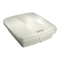
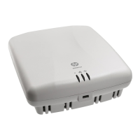
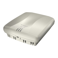
This document describes the HP MSM430, MSM460, and MSM466 802.11n Access Points, hereafter referred to as the AP. These devices are Wi-Fi Alliance authorized 802.11n/a/b/g products designed for wireless network connectivity. They can operate in either a controlled mode, managed by an HP MSM7xx controller, or in an autonomous mode as standalone access points.
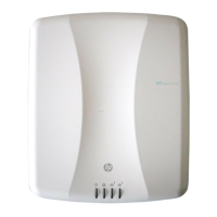
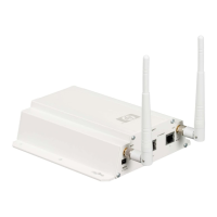
The primary function of these APs is to provide wireless network access. They support the 802.11n standard, offering high-speed wireless connectivity. The MSM430 and MSM460 models feature integrated dual-band MIMO antennas, while the MSM466 model requires external antennas, providing greater flexibility for specific deployment scenarios. All models support Power over Ethernet (PoE) 802.3af, allowing for power and data transmission over a single Ethernet cable, simplifying installation.
In controlled mode, the APs establish a secure management tunnel with an HP MSM7xx controller (MSM710, MSM720, MSM760, or MSM765zl). The controller manages the APs and provides all configuration settings, centralizing network management. This mode is ideal for larger deployments where multiple APs need to be managed efficiently. The APs automatically connect to a controller if default settings are used and both devices are on the same subnet.
In autonomous mode, the AP operates as a standalone device, managed via its web-based management tool. This mode is suitable for smaller deployments or situations where a dedicated controller is not required. The web-based management tool, accessible through a web browser, allows for initial configuration, including setting up basic wireless protection and assigning IP addresses.
The APs feature two radios. The MSM430 and MSM460 provide 802.11n/a on Radio 1 and 802.11n/b/g on Radio 2. The MSM466 provides 802.11n/a on Radio 1 and 802.11n/a/b/g on Radio 2. For optimal performance, the MSM460 and MSM466 support 3x3 MIMO three-spatial-stream 802.11n, while the MSM430 supports 3x3 MIMO two-spatial-stream 802.11n.
The APs offer flexible installation options, including mounting on a wall, an electrical box, or a suspended ceiling. The AP Bracket, which is two-sided, is mounted first, and then the AP is attached to the bracket. For suspended ceiling installations, two sets of T-bar clips are provided for recessed and flush-mount tiles. Careful attention to safety precautions, such as working safely above false ceilings and using non-conductive step ladders, is emphasized during installation.
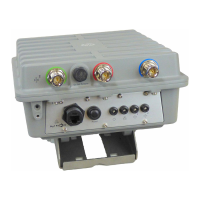
Connecting the AP involves an Ethernet cable for data and power (via PoE). The Ethernet port is auto-sensing 10/100/1000 BaseT with an RJ-45 connector. A console port with an RJ-45 connector is also available for serial communication, though it is not typically needed for initial configuration. Users are cautioned against connecting the console port to an Ethernet switch or PoE power source to prevent damage.
For the MSM466 model, external antennas must be connected, respecting color-coding and radio designation. Specific approved antennas are listed, and users are advised to consult the Antenna Power-Level Setting Guide for regulatory compliance, especially regarding transmission power levels based on the country of use.
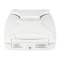
The APs provide visual feedback through status LEDs (Power, Ethernet, Radio 1, Radio 2) on the front panel. These LEDs indicate various operational states, such as power on, Ethernet activity, radio activity, startup, IP address acquisition, controller discovery, and secure tunnel establishment. In autonomous mode, the LEDs also indicate if the software failed to load or if the AP is fully operational.
Initial configuration in autonomous mode involves connecting the computer directly to the AP (or via a PoE switch/injector), configuring the computer's LAN port with a static IP address, and then accessing the web-based management tool via a browser. The process includes switching the AP to autonomous mode, logging in, changing the default password, and configuring basic wireless protection (WPA or WPA2). Users can also assign a static IP address to the AP or allow a DHCP server to assign one.
The APs are designed for indoor installation. When connecting outdoor antennas to the MSM466, proper lightning surge protection and grounding precautions are mandatory to prevent personal injury, fire, equipment damage, or voided warranty. Plenum-rated cables and attachment hardware must be used for plenum installations.
A Reset button is accessible via a hole on the bottom of the AP. A quick press and release of the button resets the AP, while pressing and holding it until the status LEDs blink three times resets the AP to factory defaults. This feature is useful for troubleshooting or reconfiguring the device.
The APs incorporate security features, including the recommendation to change the default password during initial setup. Passwords must be at least six characters long and include four different characters. For wireless protection, HP recommends configuring WPA or WPA2 with a preshared key of at least 20 characters.
To secure the AP physically after installation, a retention screw can be installed to anchor the AP Bracket to the AP. Additionally, a cable lock can be attached in its designated hole, or the supplied AP Padlock Bracket can be used with a user-supplied padlock for enhanced physical security.
The web-based management tool provides access to various settings, organized with menus and sub-menus (e.g., VSC, Wireless, Network, Security, Authentication, Management, Status). This interface allows for ongoing configuration and monitoring of the AP's operation.
For controlled mode, the APs automatically attempt to establish a connection with a controller. If a conflict arises (e.g., discovery replies from multiple controllers with the same priority), the LEDs will indicate this state, prompting the user to resolve the conflict.
The documentation emphasizes the importance of professional installation and adherence to local regulations, including building and wiring codes, safety, channel, power, indoor/outdoor restrictions, and license requirements for the intended country. The end user is responsible for ensuring compliance.
In case of issues, the status LEDs provide diagnostic information. For example, a Power LED that continues to blink after several minutes in autonomous mode indicates a software loading failure, suggesting a reset or power cycle of the AP, or contacting HP customer support if the issue persists.
| Wireless Standards | IEEE 802.11a/b/g/n |
|---|---|
| Frequency Band | 2.4 GHz, 5 GHz |
| Power over Ethernet (PoE) | Yes |
| Maximum Data Rate | 300 Mbps |
| Data Transfer Rate (maximum) | 300 Mbps |
| Networking Standards | IEEE 802.11a/b/g/n |
| Antenna Gain Level (max) | 3 dBi |
| Power Consumption (max) | 12.95 W |
| Antennas | Internal |
| Frequency Band Range | 2.4 GHz, 5 GHz |
| Security Algorithms | WPA, WPA2 |
| Input Voltage | 48 V |
| Operating Temperature (T-T) | 0 - 40 °C |
| Operating Relative Humidity (H-H) | 5% to 95% |
| Security Features | WPA, WPA2, WEP, 802.1X |
| Management | SNMP |
| Ethernet Ports | 1 x 10/100/1000 |
| Number of Users | 128 |