14. Hand tighten the threads between sealing nut (1)
and clamp ring (3), until the cable is firmly
anchored.
CAUTION: Do not over tighten. Do not tighten
with tools.
Installing cabling
According to your needs and local electrical codes
and regulations, run Ethernet cabling, body ground
wire, and any separate grounding wires as needed
for antenna lightning arresters as described in the
respective antenna guide, to where the AP will be
installed. For the Ethernet cable, allow for an extra
0.6 meters (2 feet) for connector attachment and drip
loops. Install an Ethernet surge suppressor (not
supplied) according to its instructions at the location
where the Ethernet cable enters the building. This might
not be necessary if the outdoor cable run is very short;
for example, when the AP is mounted on an outdoor
wall. The AP includes a built-in Ethernet surge
suppressor for its end of the Ethernet cable.
Mounting the AP
The AP can be mounted on a pole or on a wall.
Pole installation
IMPORTANT: The AP and antennas can be mounted
on a pole with a diameter of 32 to 57 mm (1.25 to
2.25 inches). The pole must be capable of supporting
the AP and antennas at the maximum anticipated wind
loading.
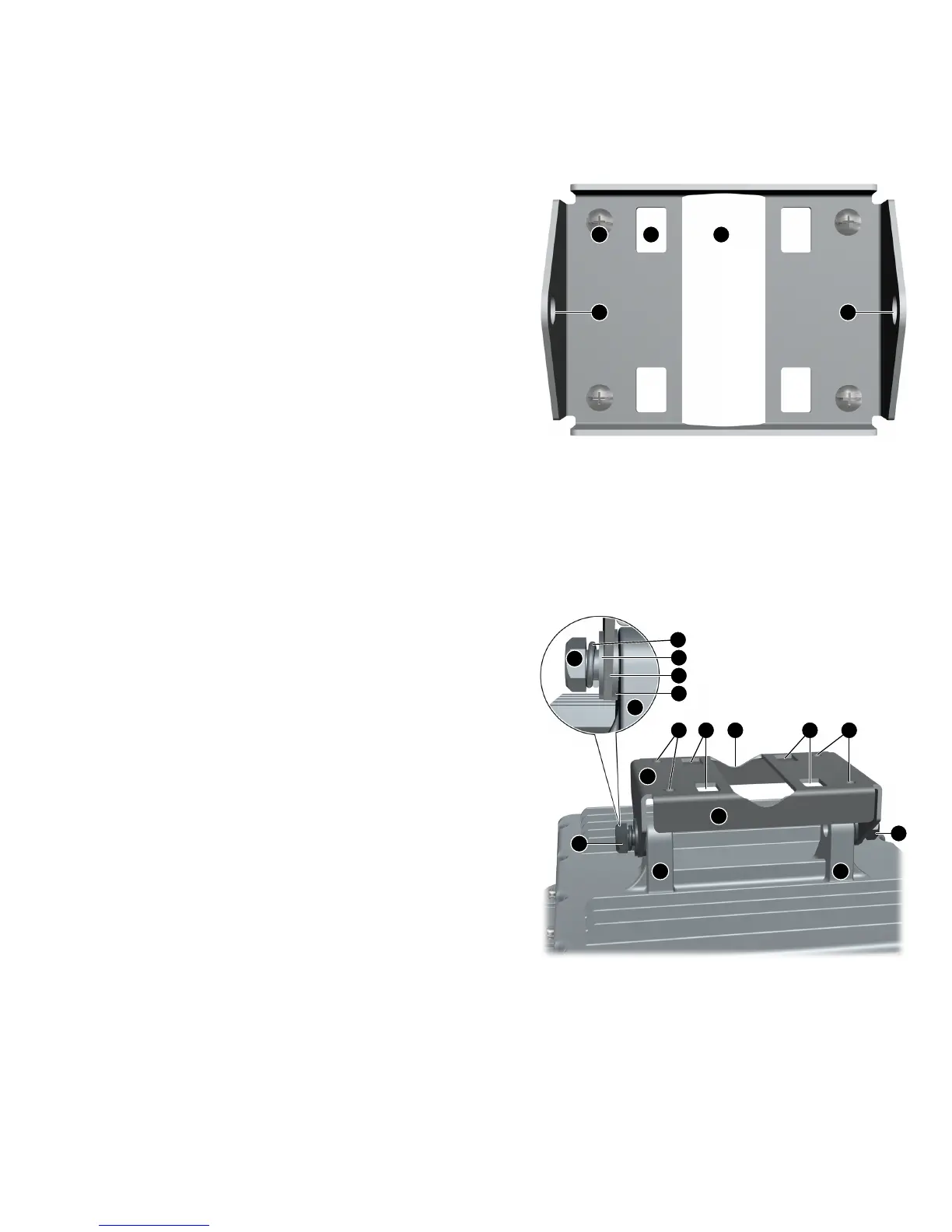
1. Locate the AP mounting bracket. See
Figure 4 (page 4). Note that the four screw holes
(1) are not used for pole mounting, only wall
mounting.
Figure 4 Mounting bracket
3. Pole cut out1. Screw holes (x4) (screws shown)
4. Bracket bolt hole (x2)2. Pole clamp slot (x4)
The image key references in Step 2 through Step
6 reference Figure 5 (page 4).
Figure 5 AP with mounting bracket attached
6. Bracket post (x2)1. Bracket bolt (x2)
7. Screw hole (x4)2. Lock washer (x2)
8. Pole clamp slot (x4)3. Flat washer (x2)
9. Pole cut out4. Bracket
5. Flat washer (x2)
Page 4
 Loading...