Testing the wireless network
In the following example, the network has a DHCP
server and an Internet connection. Broadband routers
typically include a DHCP server.
1. Disconnect your computer from the PoE switch or
injector.
2. Power off the AP by disconnecting the Ethernet
cable from the AP or PoE power source.
3. Use an Ethernet cable to connect the switch or
the data in port of the injector to the network.
4. Reconnect and power on the AP. Use an Ethernet
cable to reconnect the AP to the PoE switch or the
data and power out port of the injector.
5. Enable the wireless network interface of your
computer, and ensure that it is set to obtain an IP
address and a DNS address automatically as
described in your operating system
documentation.
6. By default, the AP creates a wireless network
named HP in the 5 GHz band for 802.11n and
802.11a users. Connect your computer to this
wireless network, specifying the pre-shared key
you set earlier in Step 2 of “Configuring basic
wireless protection” (page 9).
7. Confirm that you can browse the Internet using
the wireless network.
Performing additional configuration
Configure your computer LAN port and connect it to
the same network as the AP. Re-launch the AP
management tool at https://<IP address> where <IP
address> is the AP IP address from “Assigning an IP
address to the AP” (page 9).
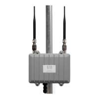
Antennas
For antenna installation information, see the respective
antenna guide. Important safety information is included
in each antenna guide.
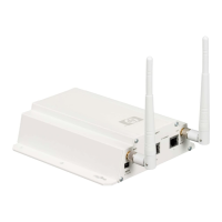
Available antennas
Only the following antennas are approved for use with
the AP. Compatible indoor antennas are shown for
the benefit of those who choose to install an AP in an
indoor location.
NOTE: For indoor installations, indoor antennas can
be used with the AP; however, RP-SMA to standard N
connector adapters (not supplied) are required to
connect indoor antennas to the AP.
ElementsUseGainBandTypePart
3Outdoor6dBi2.4 GHzOmni-
directional
J9719A
3Outdoor8dBi5 GHzOmni-
directional
J9720A
3Outdoor8dBi
nl
2.4 GHz
nl
Narrow
Beam Sector
J9169A
10.7dBi5 GHz
3Outdoor10.9dBi
nl
2.4 GHz
nl
DirectionalJ9170A
13.5dBi5 GHz
3Indoor3dBi
nl
2.4 GHz
nl
Omni-
directional
J9171A
4dBi5 GHz
6Indoor2.5dBi
nl
2.4 GHz
nl
Omni-
directional
J9659A
5.9dBi5 GHz
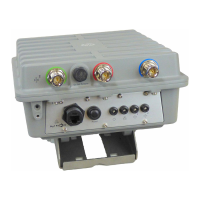
WARNING: When using the AP outdoors, you must
ensure that a lightning arrester is used on each
antenna connector (total of six). Lightening Arresters
(not supplied) are available from HP (J8996A).
CAUTION: Depending on the country of use, the
antenna selected, and your radio settings, it may be
mandatory to reduce the radio transmission power
level to maintain regulatory compliance. For specific
power limits for your country, consult the HP
MSM466-R External Antenna RF Power-level Setting
Guide available at www.hp.com/support/manuals
(search for your antenna).
NOTE: The J9169A Narrow Beam Sector Antenna
and the J9170A Directional Antenna are not certified
for use with the MSM466-R (Japan) model (J9717A).
Specifications
H: 24.99 cm (9.84 inch), W: 12.5 cm (4.92
inch), D: 21.01 cm (8.27 inch)
Dimensions
2.75 kg (6.06 lb)Weight
PoE 802.3af
nl
DC input
PoE 802.3at (required where temperatures can
fall below -20°C)
12.9 WMaximum
power rating
Operating: -40°C to 55°C (-40°F to 131°F),
Non-operating: -40°C to 70°C (-40°F to 158°F)
Temperature
Operating: 5% to 95%Relative
humidity
nl
(non-condensing)
Page 10
 Loading...