Table 5-16 RJ-45 door description and part number
Description Spare part number
RJ-45 door for use in 60 W models M57166-001
RJ-45 door for use in 80 W models M75828-001
Before removing the RJ-45 door, follow these steps:
1. Prepare the computer for disassembly (see Preparation for disassembly on page 30).
2. Remove the bottom cover (see Bottom cover on page 30).
3. Remove the battery (see Battery on page 31).
4. Remove the solid-state drives (see Solid-state drive on page 33).
5. Remove the heat sink (see Heat sink on page 38).
6. Remove the fans (see Fans on page 40).
7. Remove the system board (see System board on page 44).
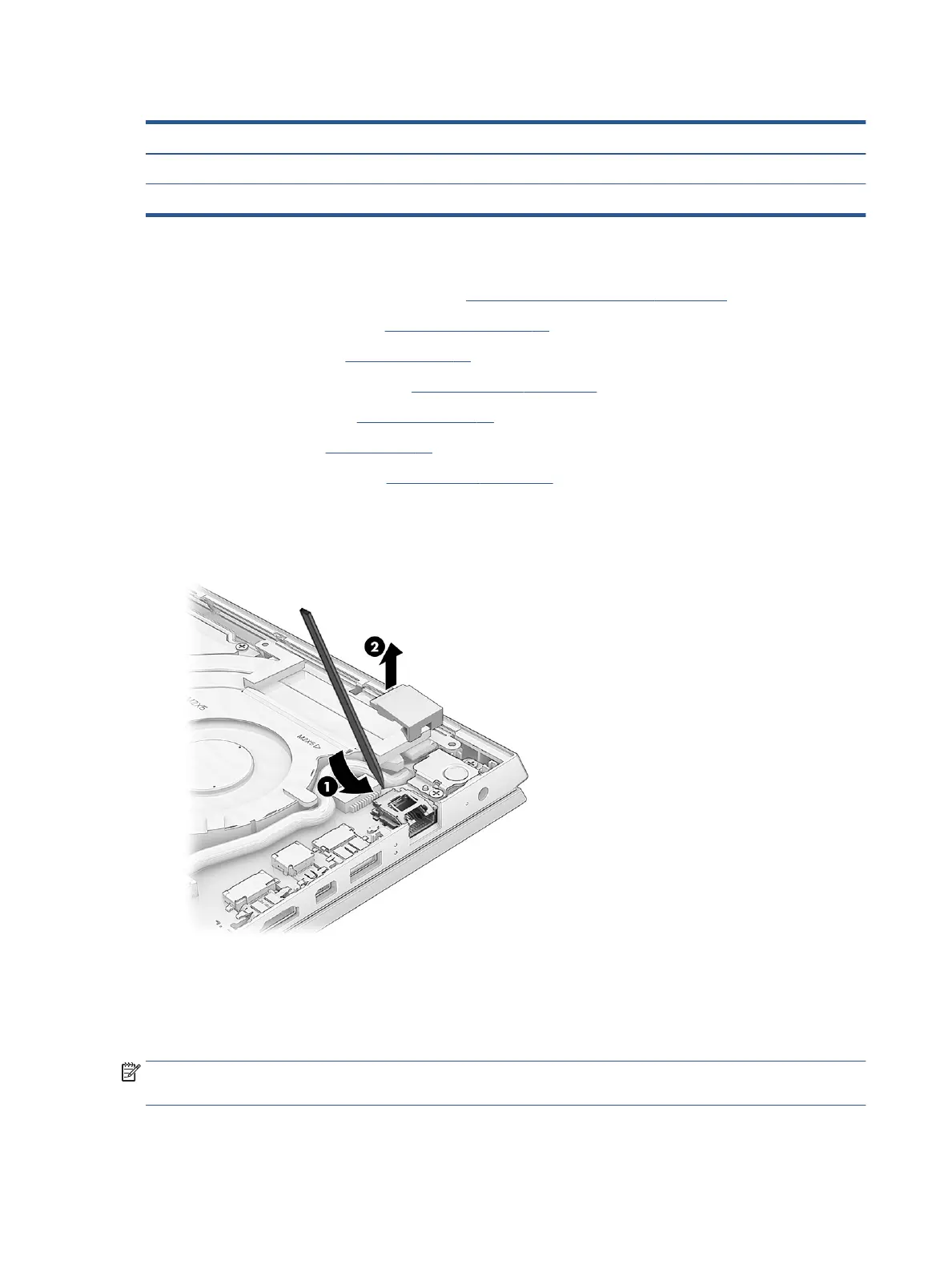
Remove the RJ-45 door:
▲ From the inside of the computer, insert a at tool under the RJ-45 door (1), and then lift the door up to
remove it (2).
Reverse this procedure to install the RJ-45 door.
Display assembly
To remove and disassemble the display assembly, use these procedures and illustrations.
NOTE: The display assembly is available as a spare part only at the subcomponent level. For display
assembly spare part information, see the individual removal subsections.
Before removing the display panel, follow these steps:
52 Chapter 5 Removal and replacement procedures for authorized service provider parts