Components, parts and materials containing
radioactive substances
List the type and size of the tools that would typically be used to disassemble the product to a point where components
and materials requiring selective treatment can be removed.
Tool Size (if
applicable)
Description #1
Description #2
3.0 Product Disassembly Process
3.1 List the basic steps that should typically be followed to remove components and materials requiring selective treatment:
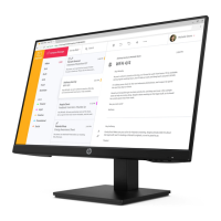
1. Lay the Monitor on the desk, Unlock the 3 screws which fix the stand with the screw driver
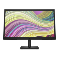
2. Unlock the 8 screws which fix the chassis
3. Take out the bezel with hand
4. Take out the keypad PCBA with hand
5. Take out the back cover with hand
6. Unlock the 4 screws which fix the panel
7. Take out the LED light and the LVDS connector from Panel
8. Separate chassis assembly and panel
9. Unlock the 2 screws which fix power socket to the chassis Unlock the 2 screws which fix the IF board to the chassis
10. Unlock the 5 screws which fix the IF & Power PCBA
11. Take out the LED light、the keypad and the LVDS connector from PCBA
3.2 Optional Graphic. If the disassembly process is complex, insert a graphic illustration below to identify the items
contained in the product that require selective treatment (with descriptions and arrows identifying locations).
Below action which may easily damage product .please notice it
Monitor on
the desk,
Unlock the
3 screws
which fix
the stand
with the
screw
Crossing
Screw
Driver
8 screws
which fix
the chassis
Crossing
Screw
Driver
EL-MF877-00 Page 2
Template Revision B
PSG instructions for this template are available at EL-MF877-01